- Mechanism/Machine Design
- Electro-mechanical engineering
- SOLIDWORKS
- Arduino IDE
- Circuitry
- Machining
- FDM 3D Printing
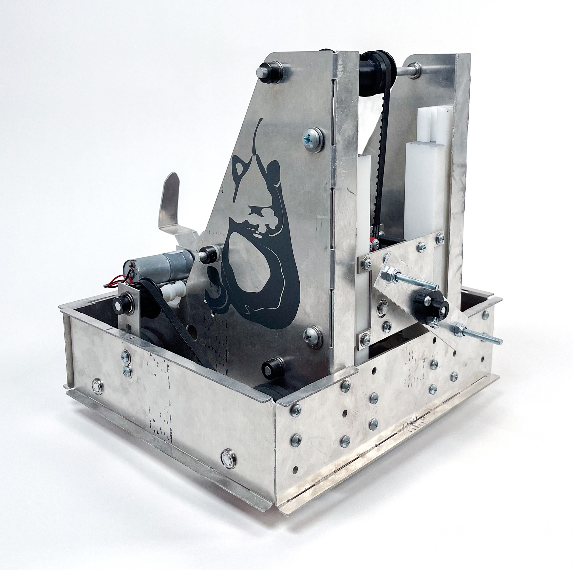
PearCat is a robot created for 2.007: Design and Manufacturing I, a class structured around an annual class competition; each year, the staff create a themed gameboard holding various objectives and obstacles, and students are tasked with ideating, designing, and manufacturing robots that can tackle these challenges to obtain points within a strict time limit and building constraints.
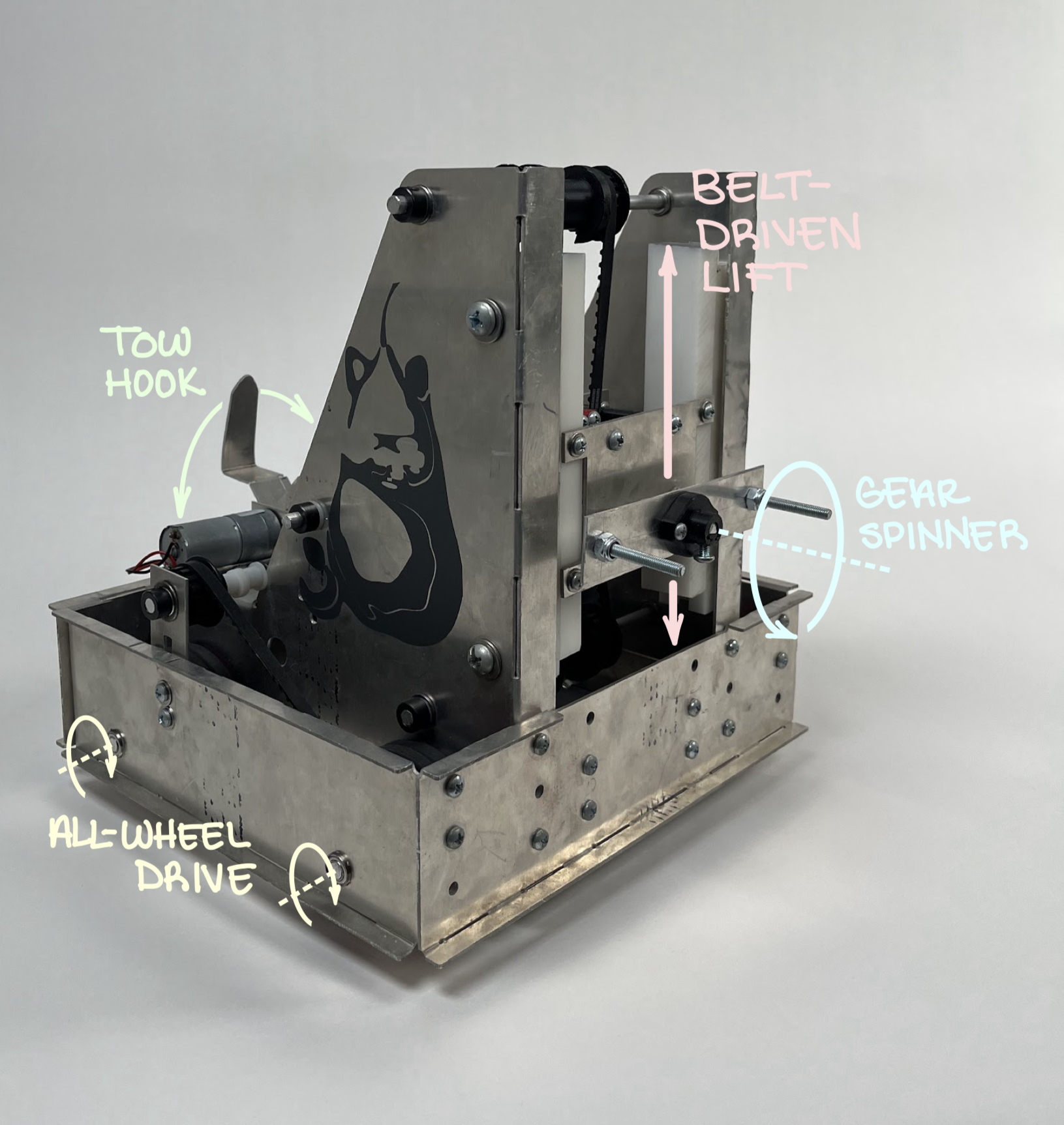
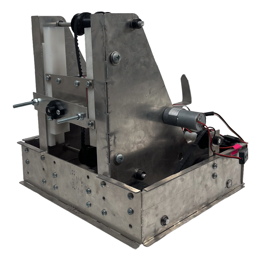
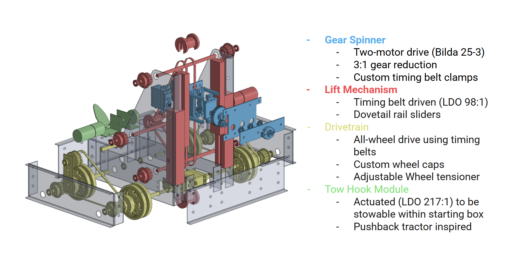
PearCat scored points primarily by spinning gear-driven platforms of varying heights around the board, as well as hooking onto and pulling a swiveling point multiplier. To achieve this, I built four main mechanisms: belt-driven lift, two-motor gear spinner, belted all-wheel drive, and actuated tow hook. PearCat was awarded the Animatronic Oz Prize for the coolest/most complex/most intricate mechanisms or robots, independent of competition performance. View my design overview here, or check back later for web format!
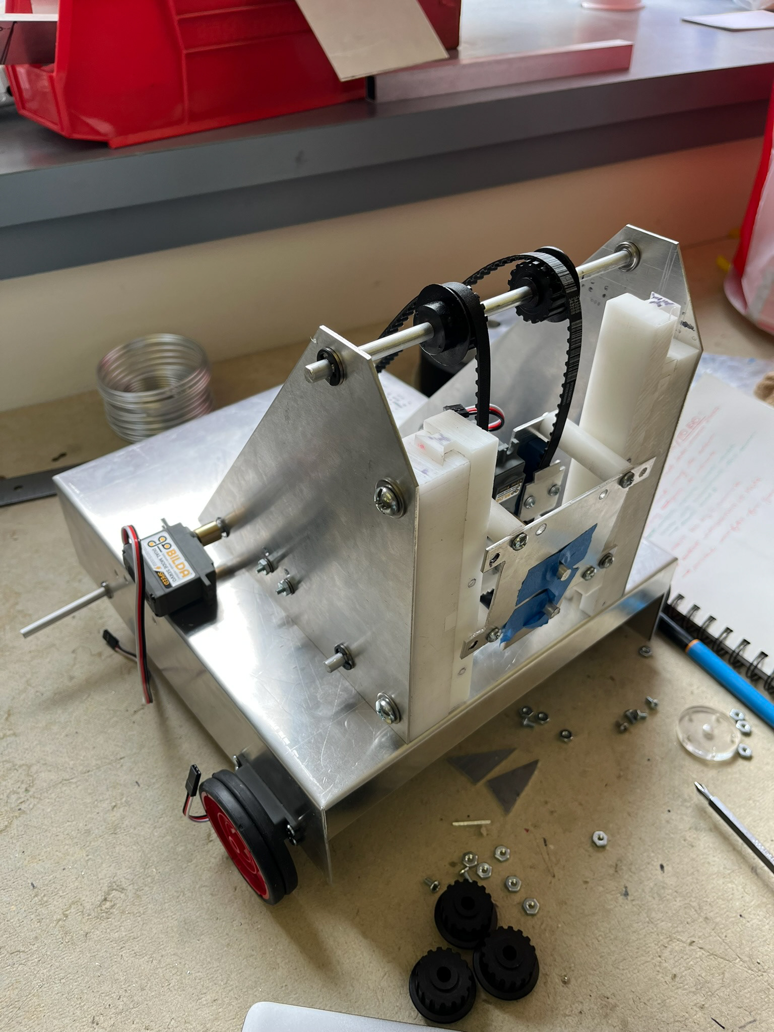
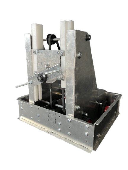
Testing mechanisms
Snippet from class competition showing PearCat's autonomous climb
Mechanisms
Lift
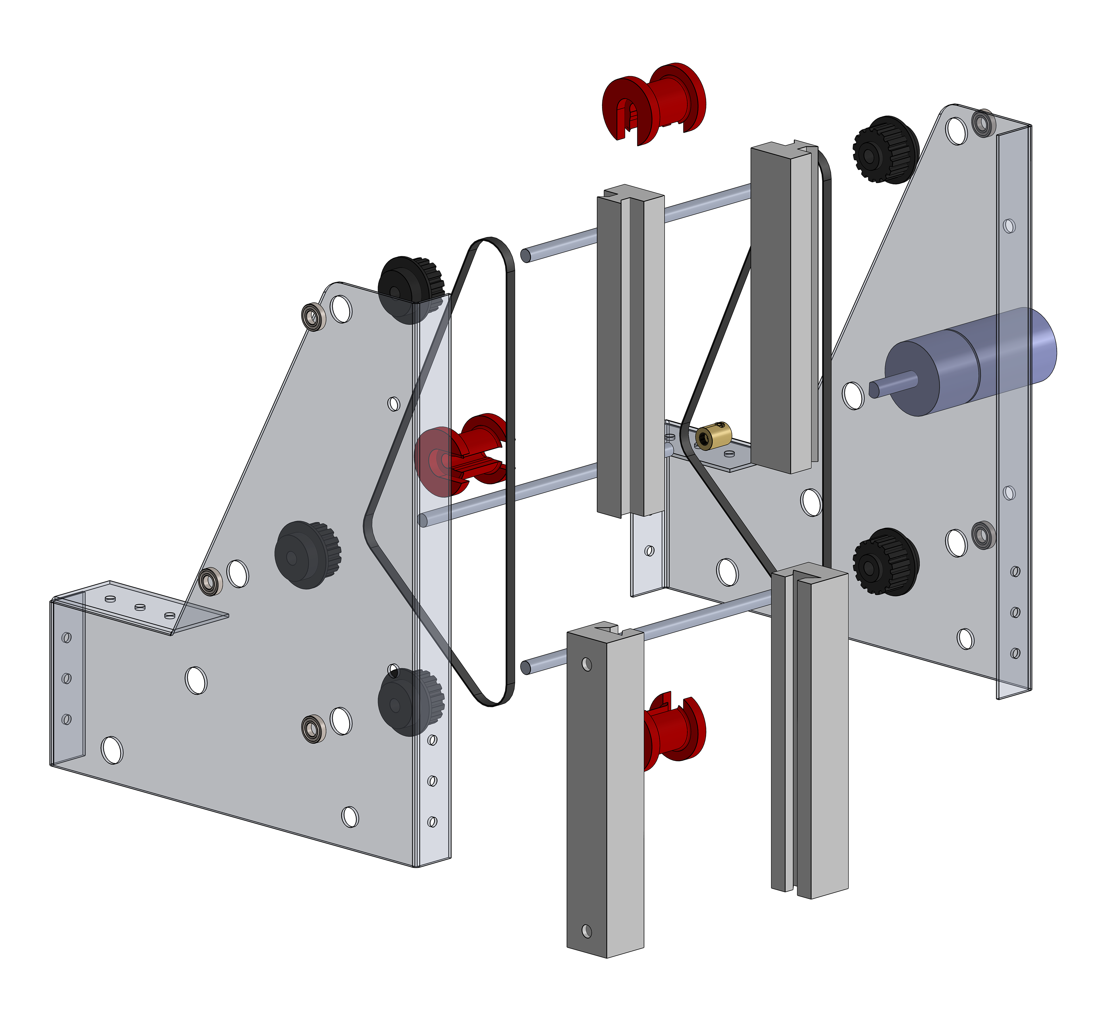
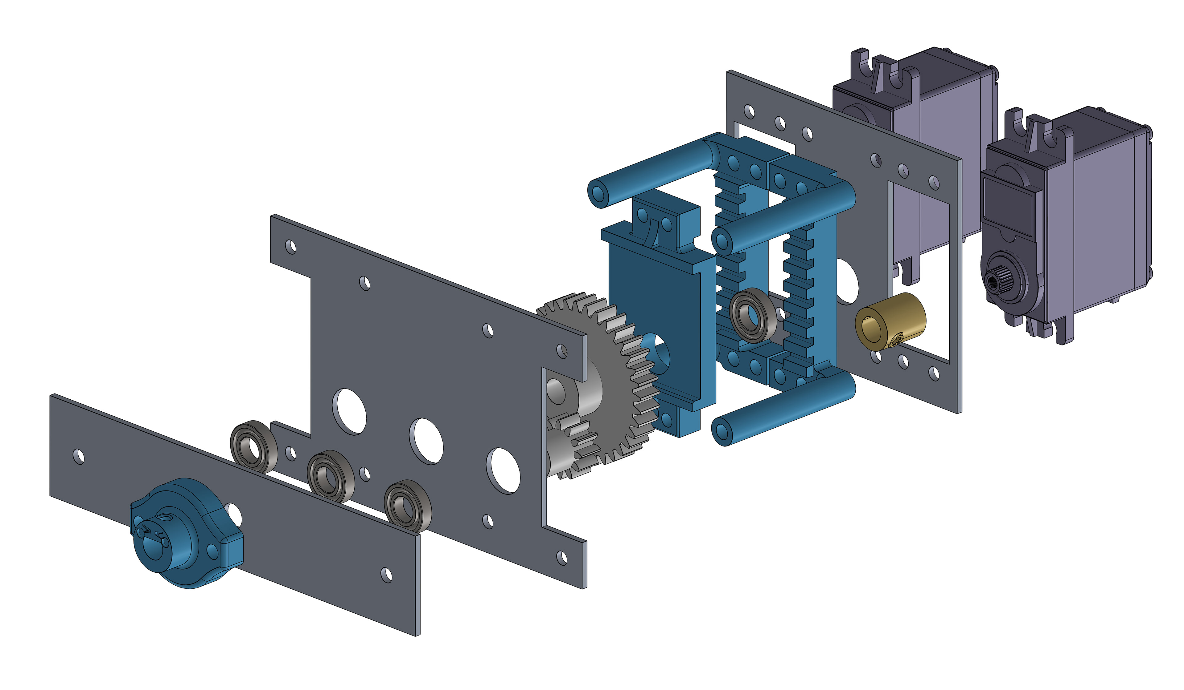
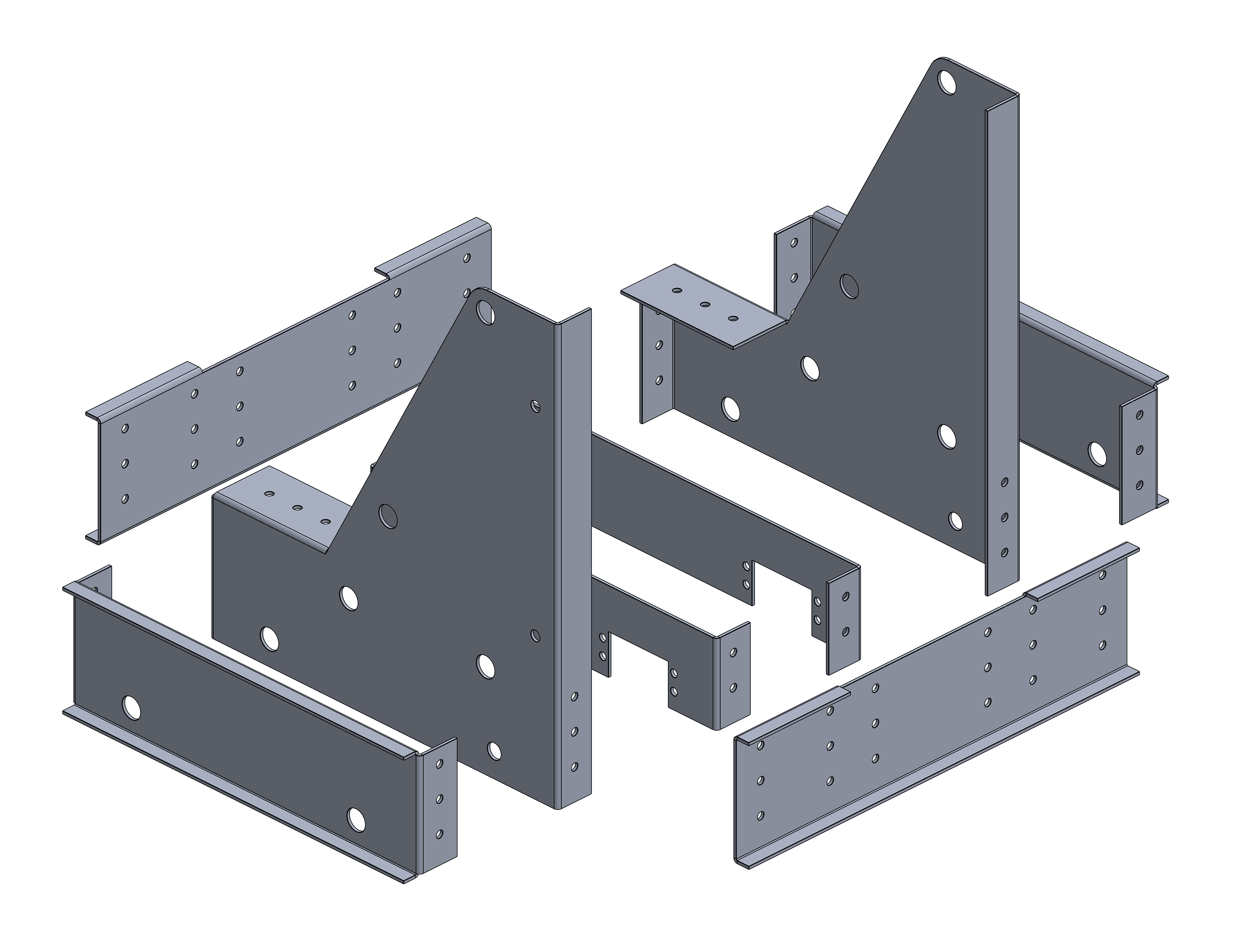
Exploded view of lift mechanism (fasteners not pictured for visual clarity)
Timing Belt
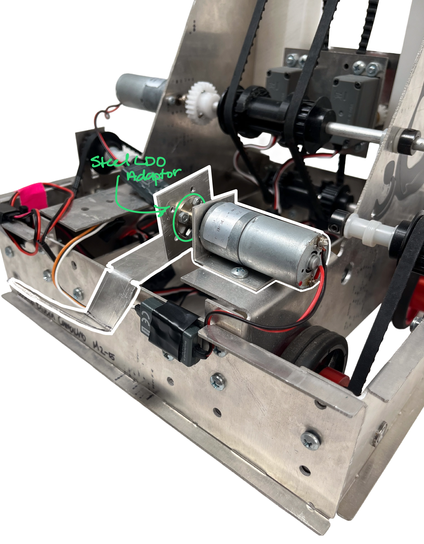
Used for quick and precise power transmission from motor to vertical movement - mechanism powered by an LDO 98:1 motor
Dovetail rail sliders
Offered smooth vertical movement, while stiffly constraining other directions. Milled out of Delrin because of its low friction coefficient (Thanks for the help Scott!)
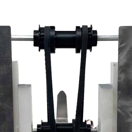
Snap-on Belt Spacers
Prevented belts from slipping during rotation; designed to snap on to shafts for ease of assembly after lift assembly was already fastened
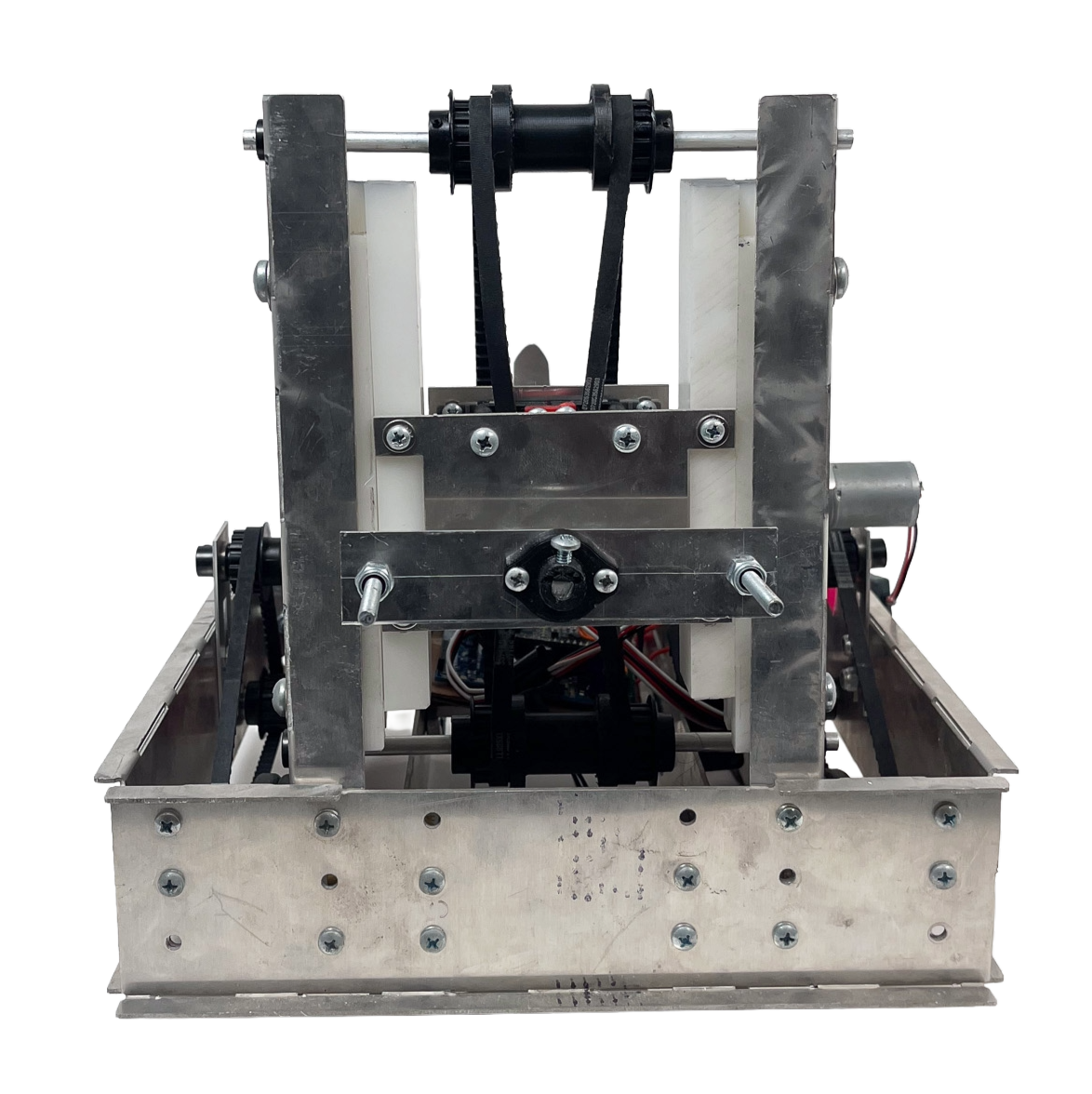
Back view of lift

Delrin dovetail sliders

Delrin dovetail sliders
Timing belt spacer
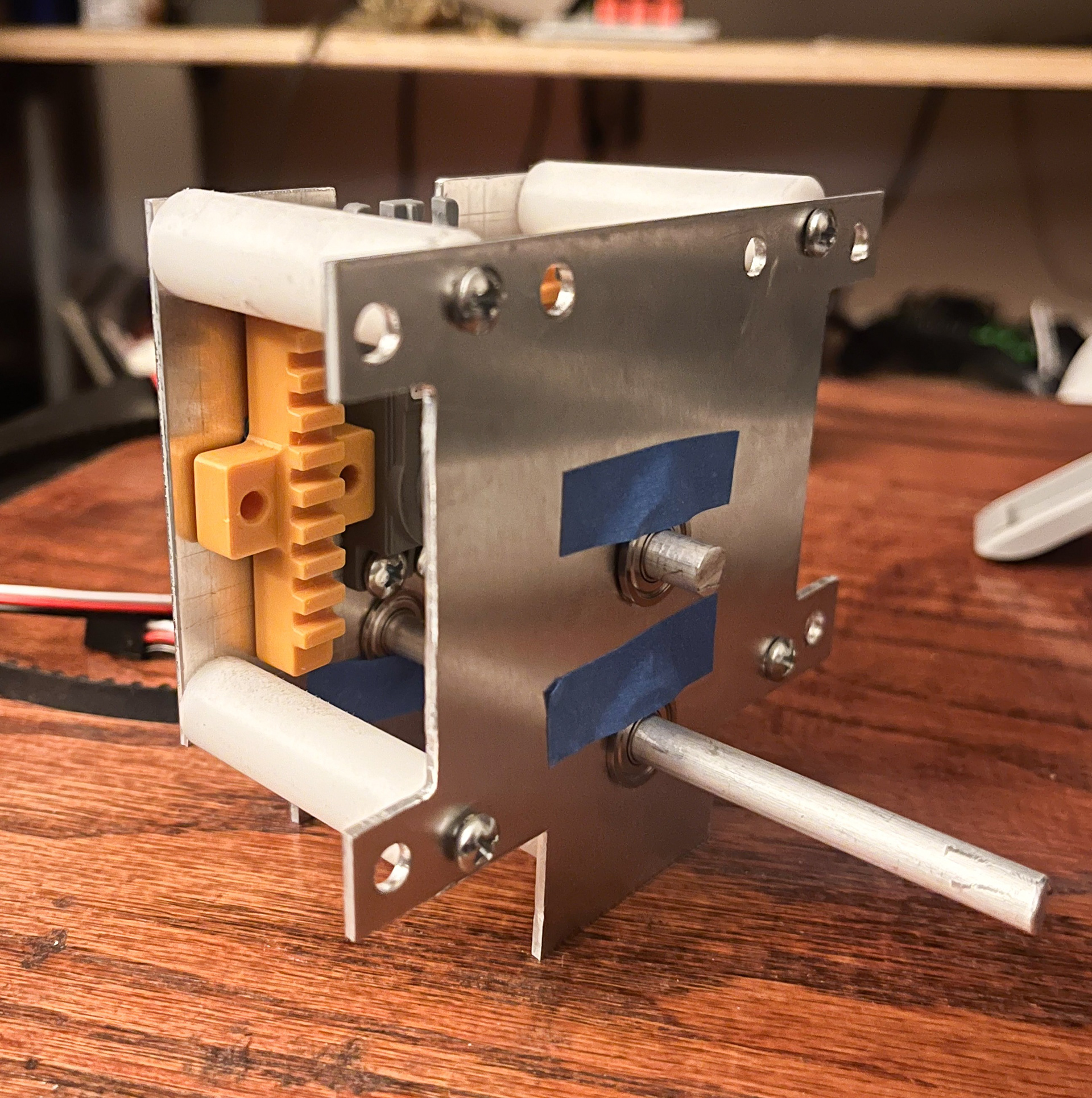
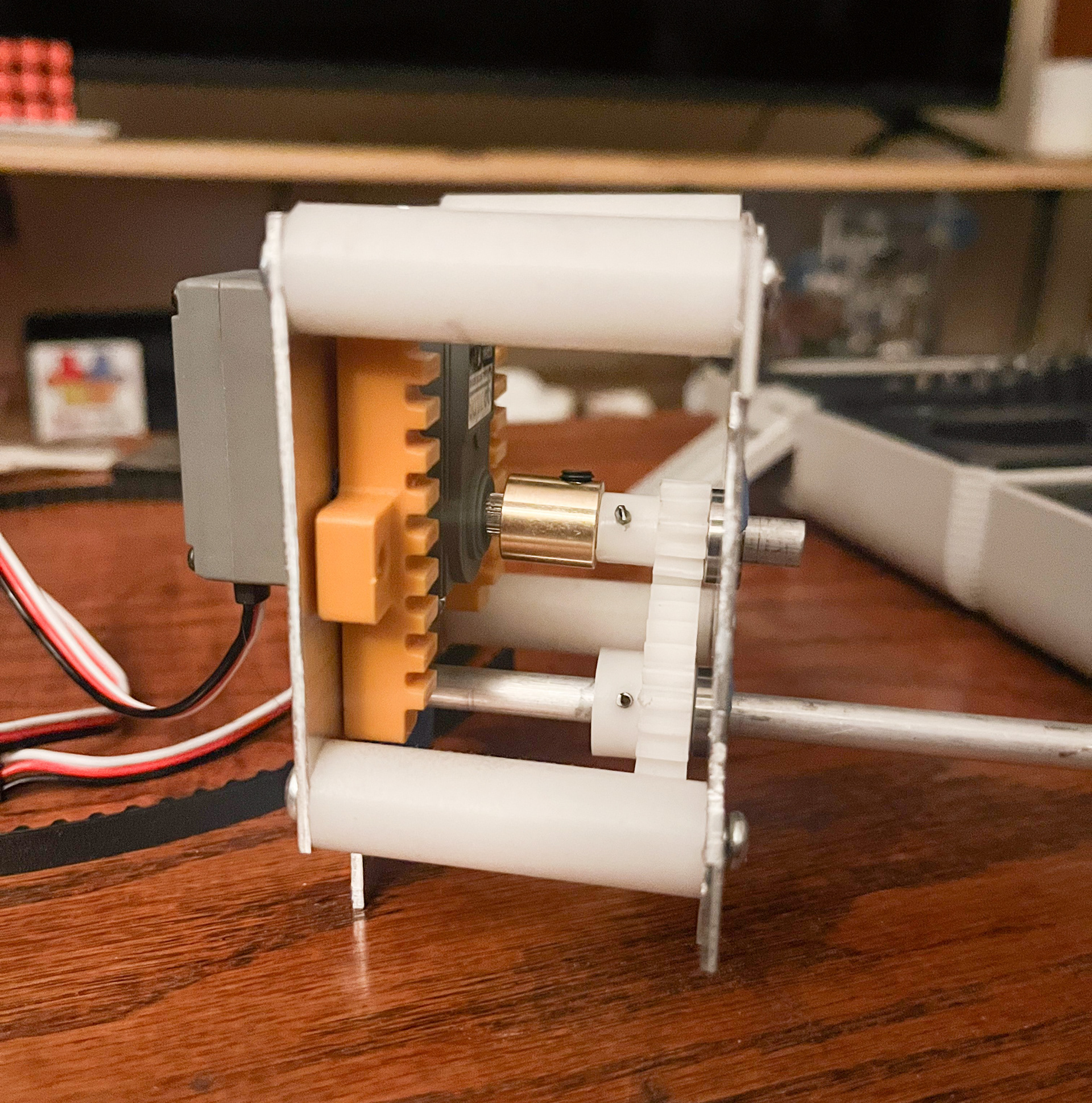
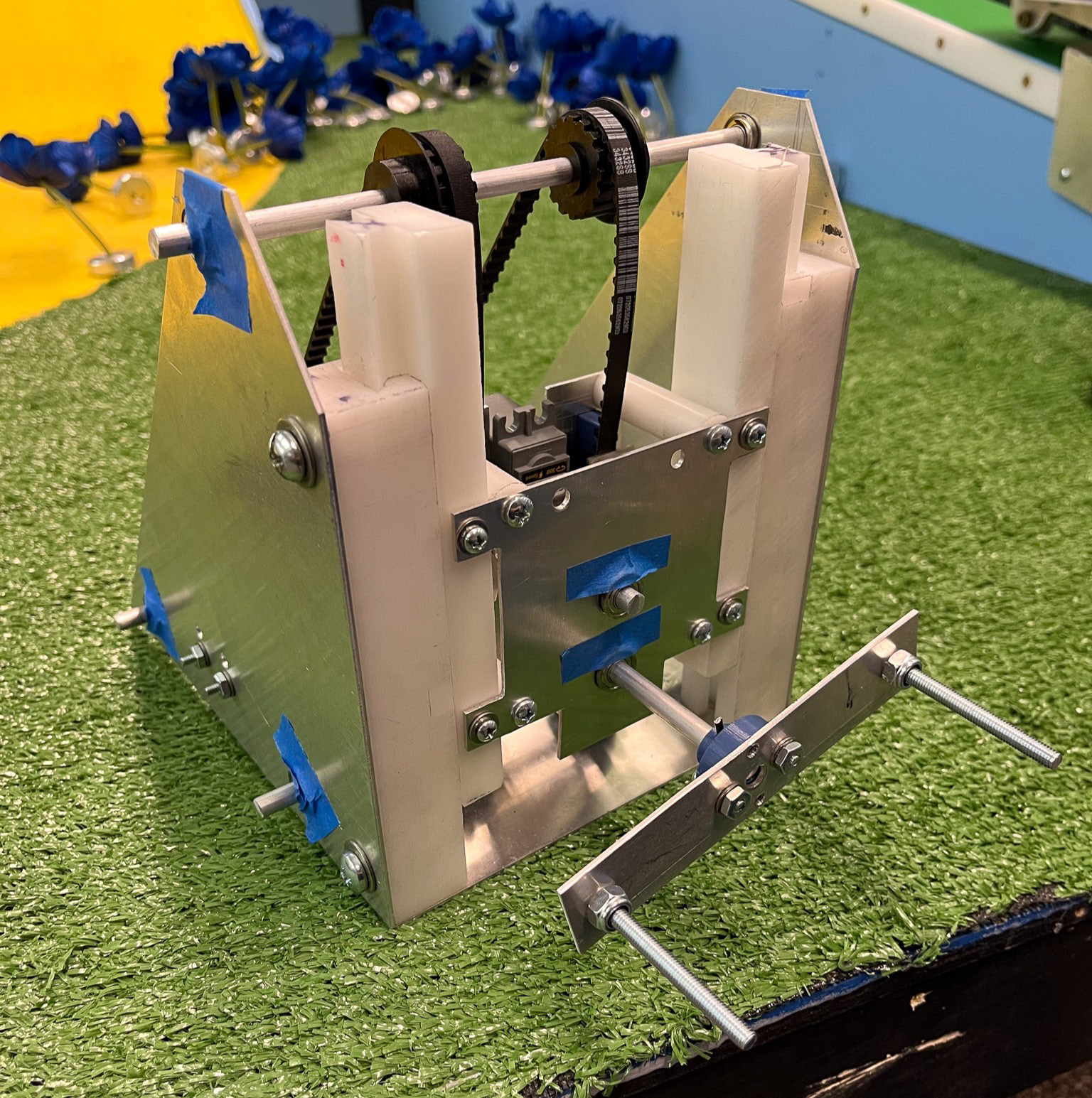
Gear Spinner
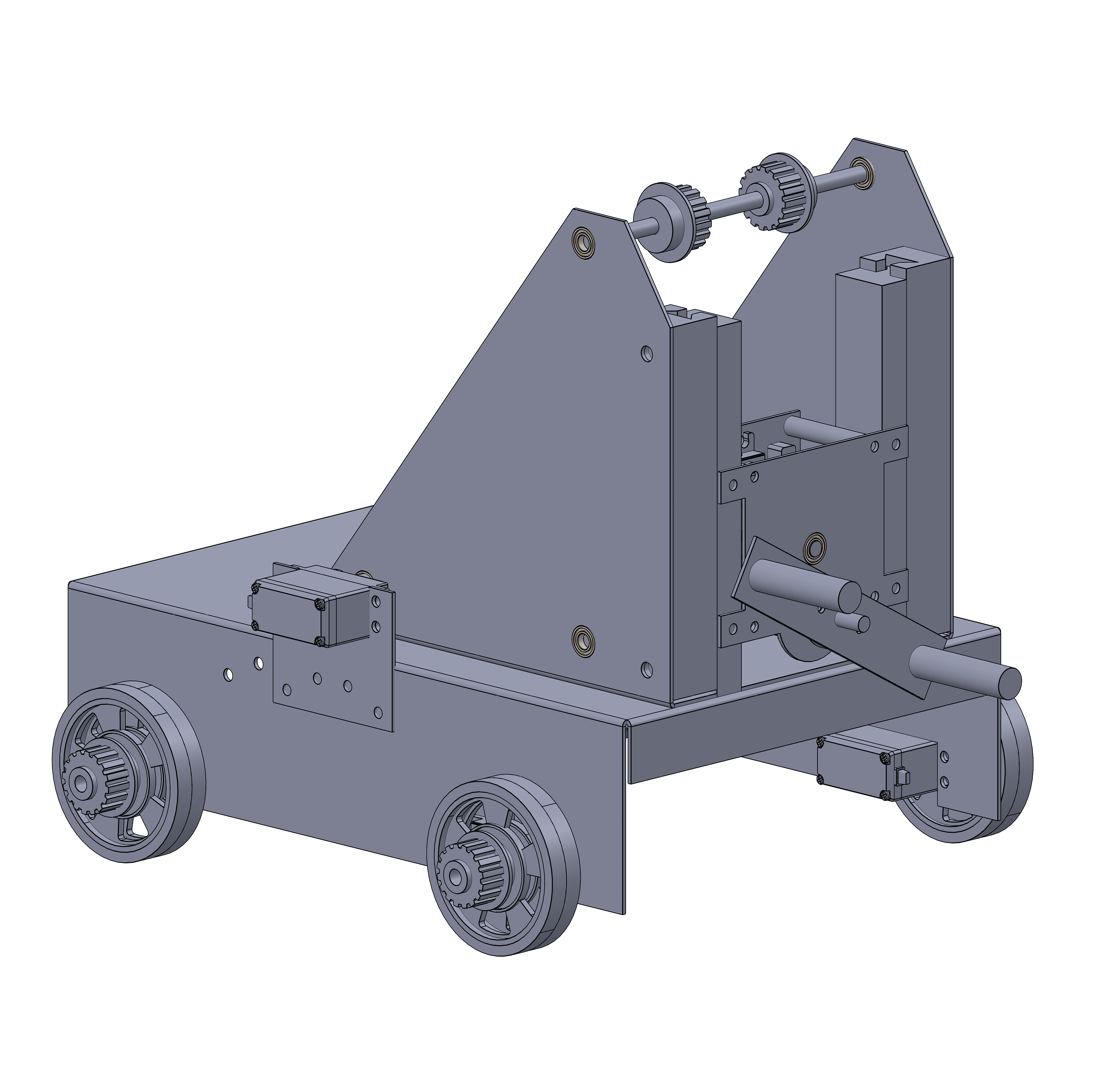
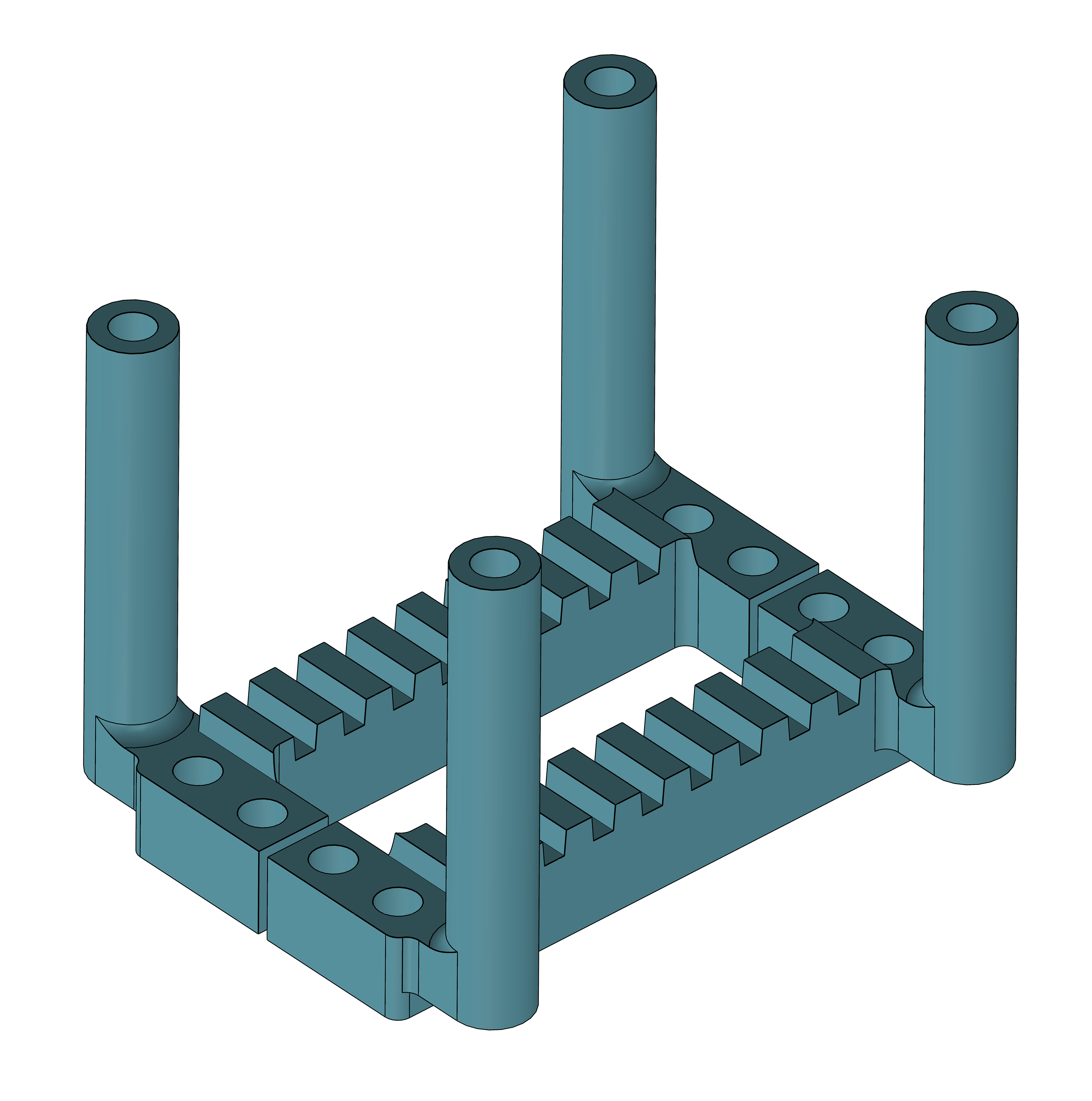
Exploded view of gear spinning mechanism (shafts and fasteners not pictured for visual clarity)
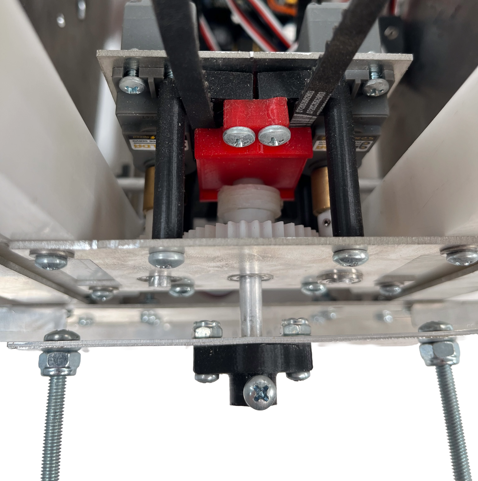
Gear spinner from above
Gear spinning claw
Gearbox
Powered by two-motor drive (Bilda 25-3/Speed) at a 3:1 gear reduction, reaching ~ 3.18 Nm and 25 RPM at peak power
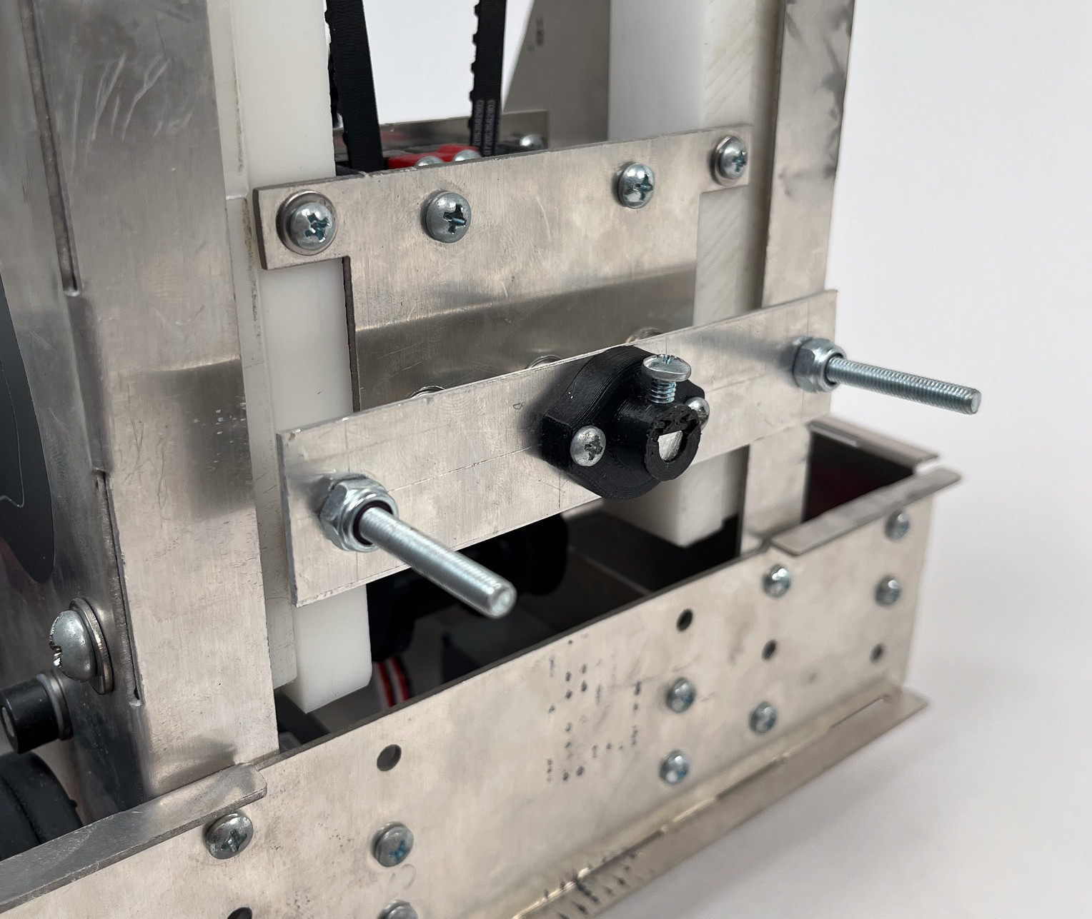
Custom timing belt clamps designed to integrate with Lift mechanism to achieve height-varying gear spinner
Spinning Claw
Output axle filed down to D-shaft to prevent slipping, since regular set screw fasteners failed
Custom D-shaft adaptor for claw assembly
Demonstration of gear spinner in action + autonomous start

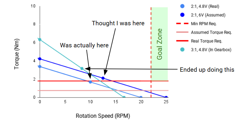
Torque-speed curve comparisons against torque requirements of game obstacles
All-wheel Drive
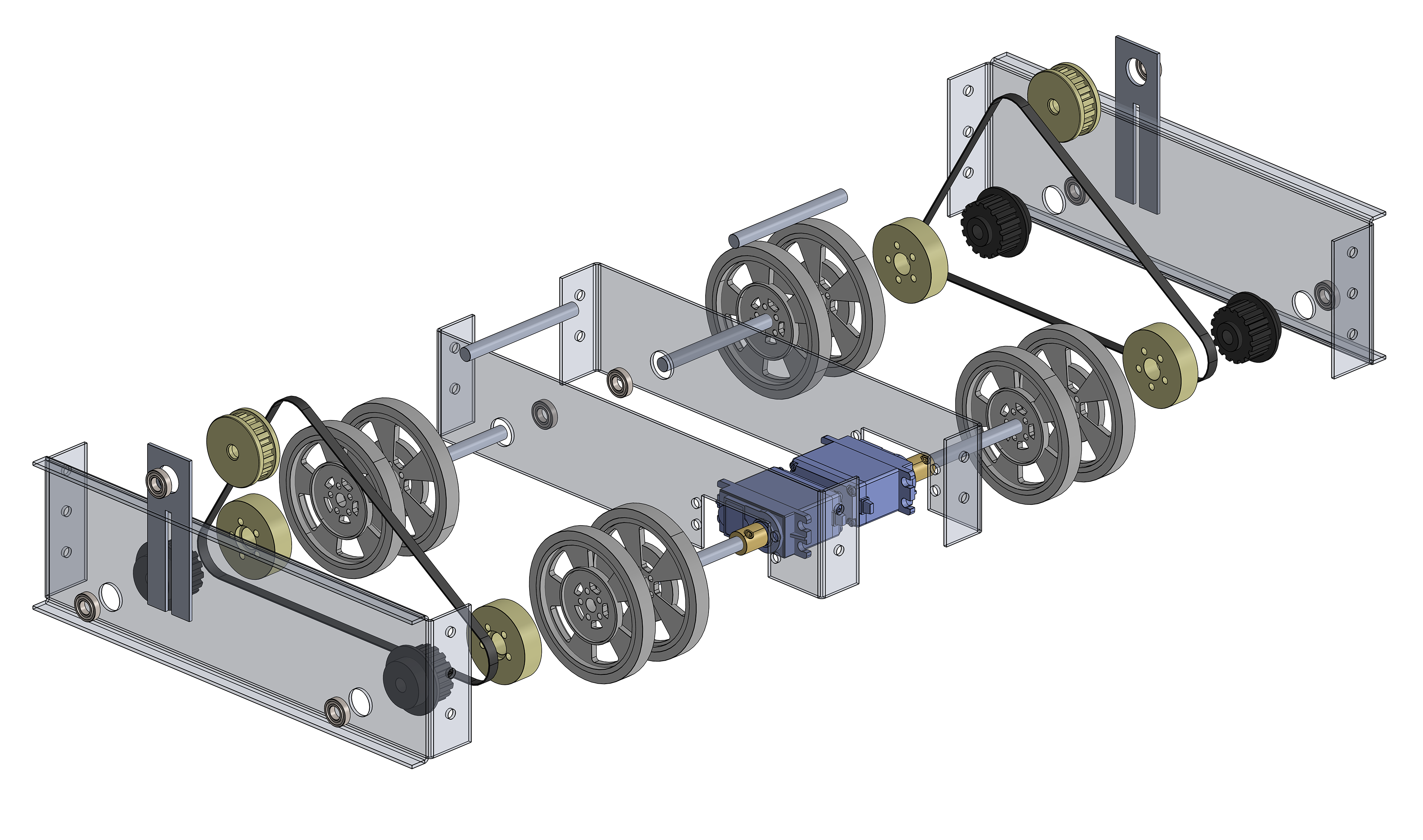
Exploded view of all-wheel drive assembly (fasteners not pictured for visual clarity)
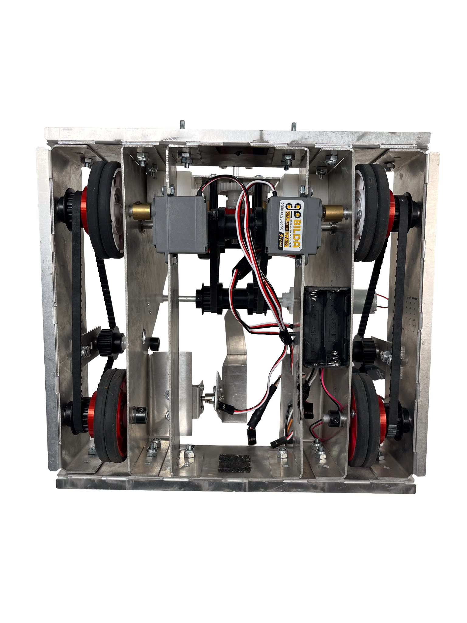
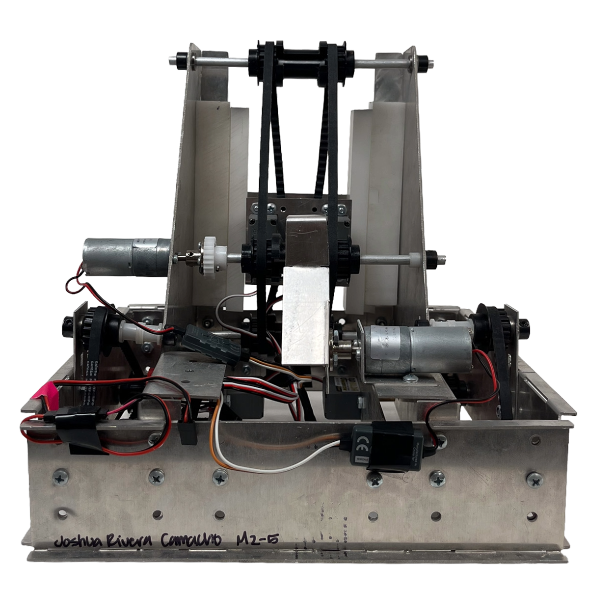
Underside of PearCat
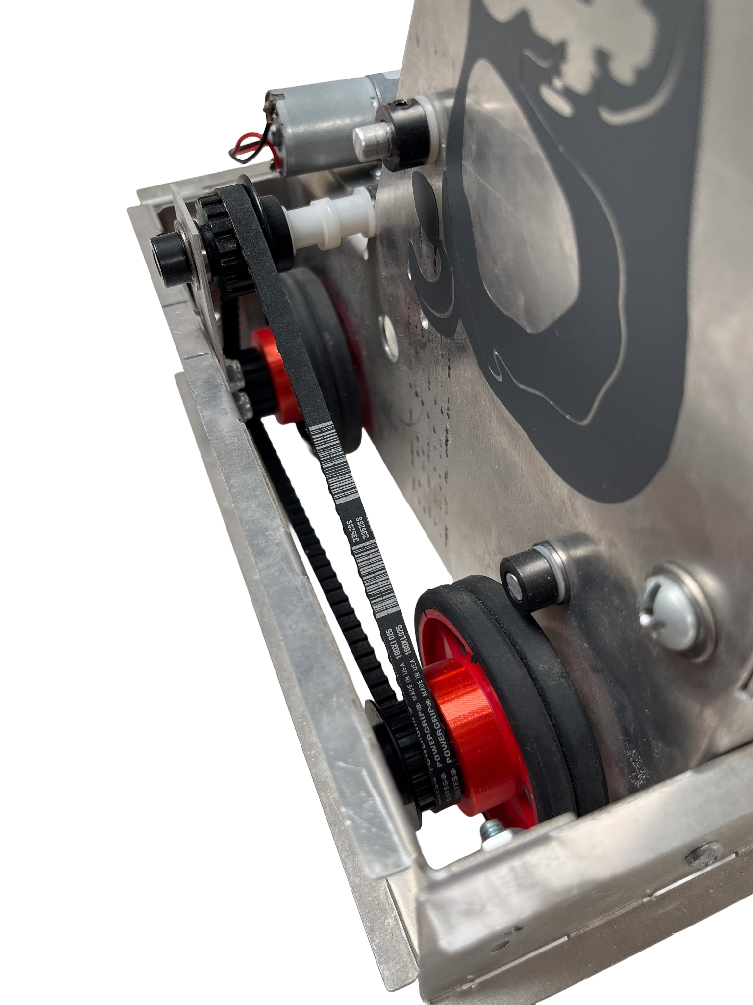
Left side drivetrain
Drivetrain
Bilda 25-3/Speed motor on each side
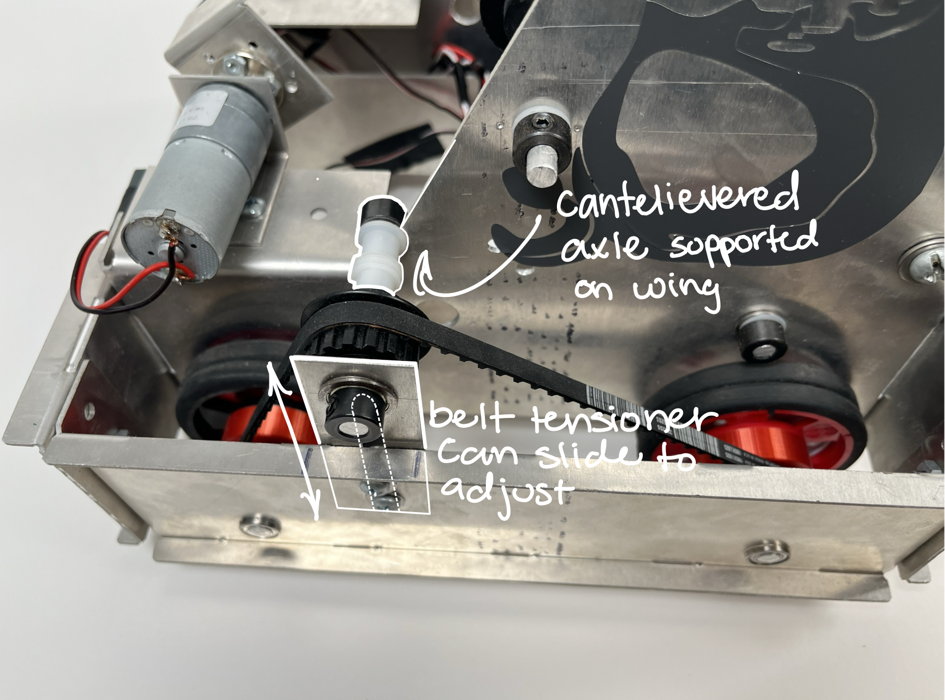
Timing belt drive to distribute power to back wheels – adjustable belt tensioners
Custom wheel caps – doubled as spacers between gears/wheels and as fasteners for wheel pairs
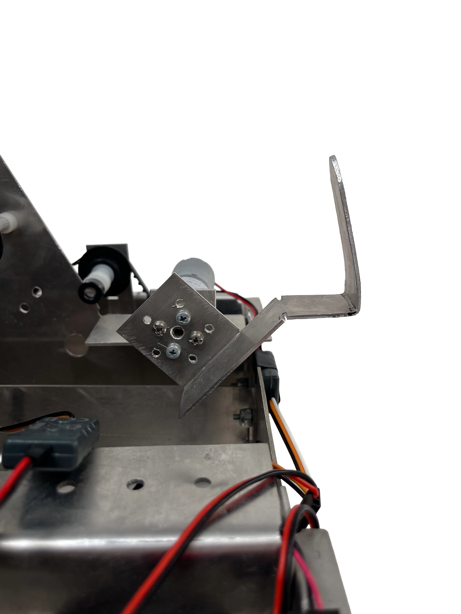
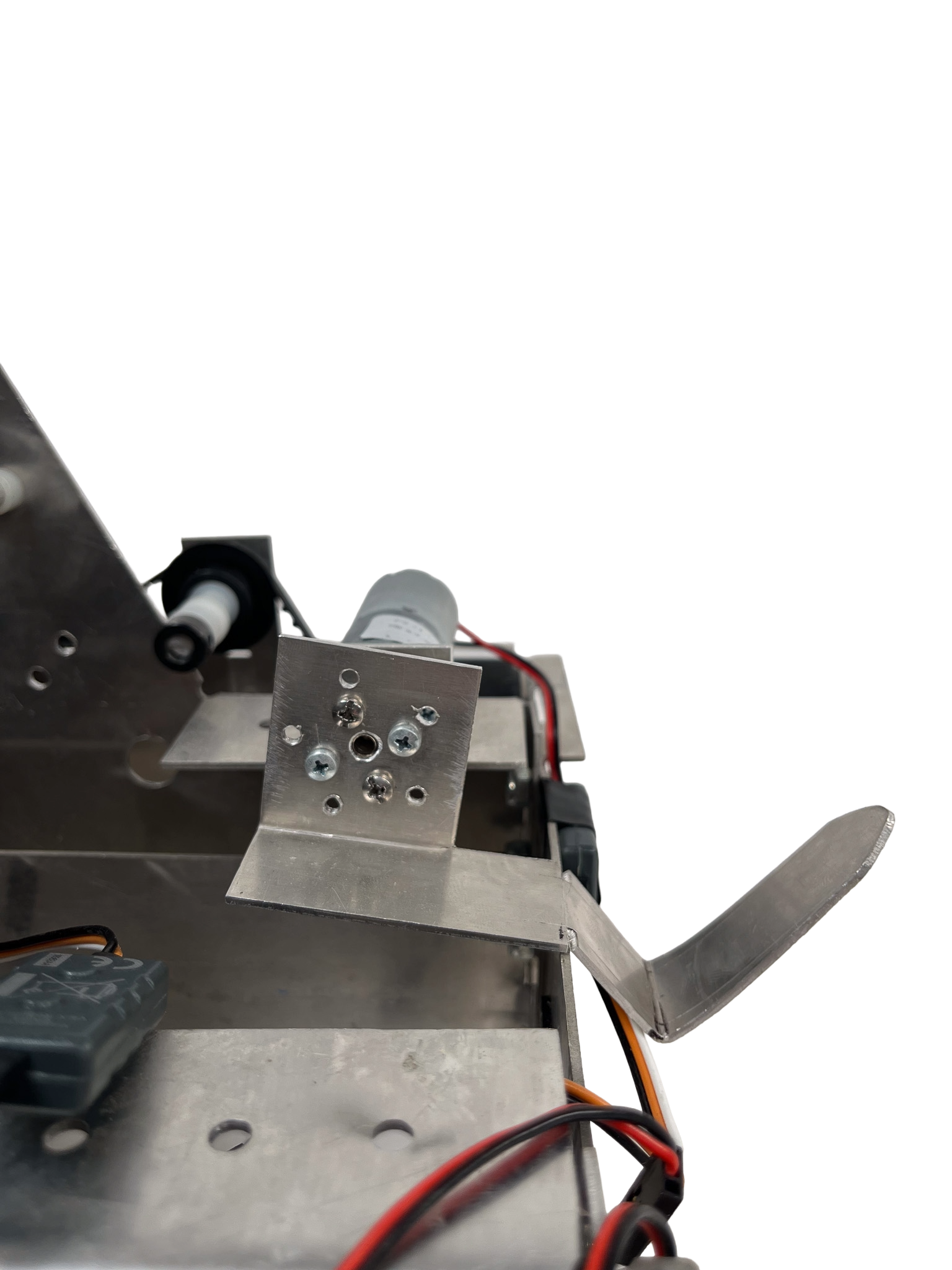
Actuated Tow Hook
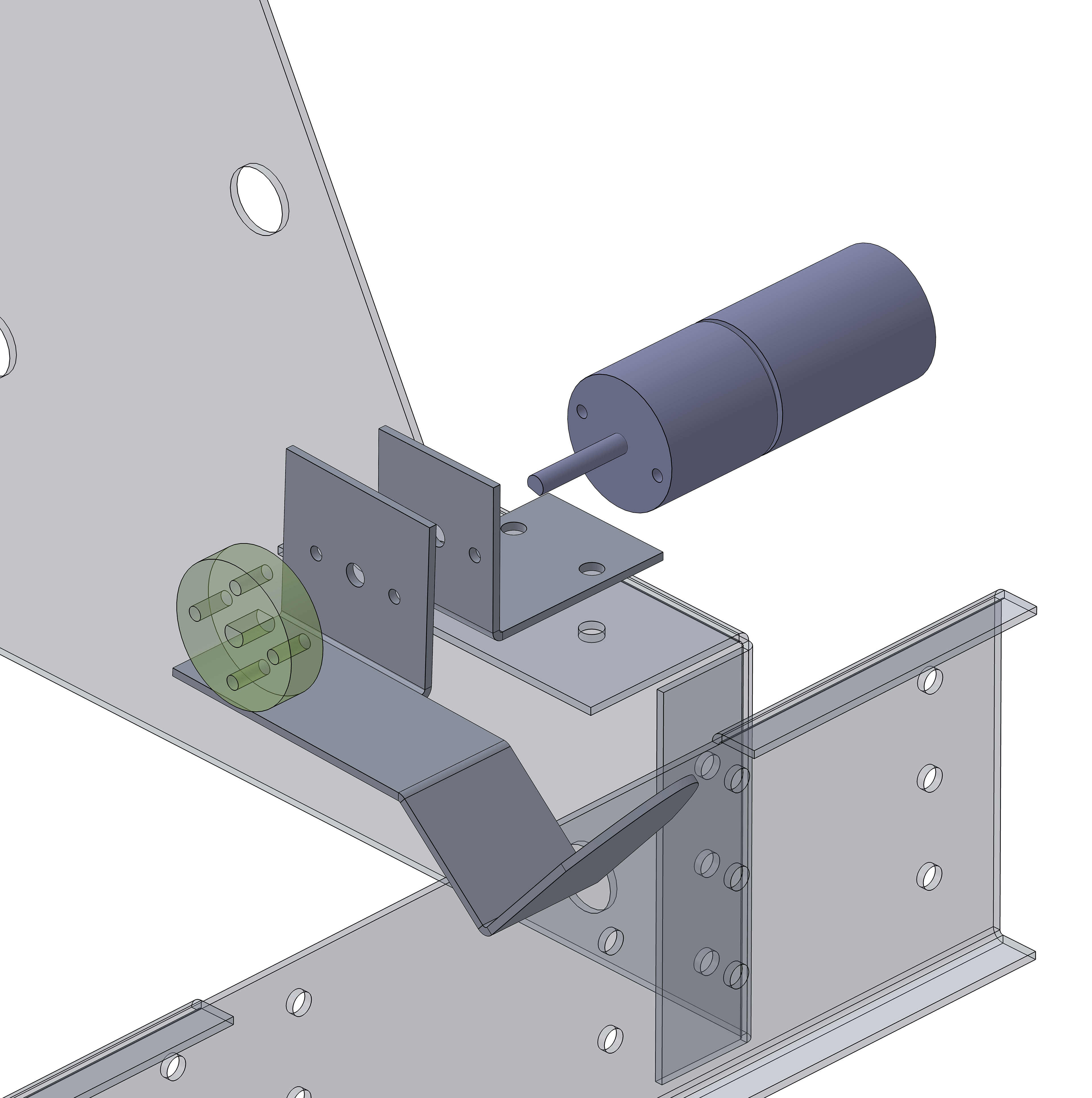
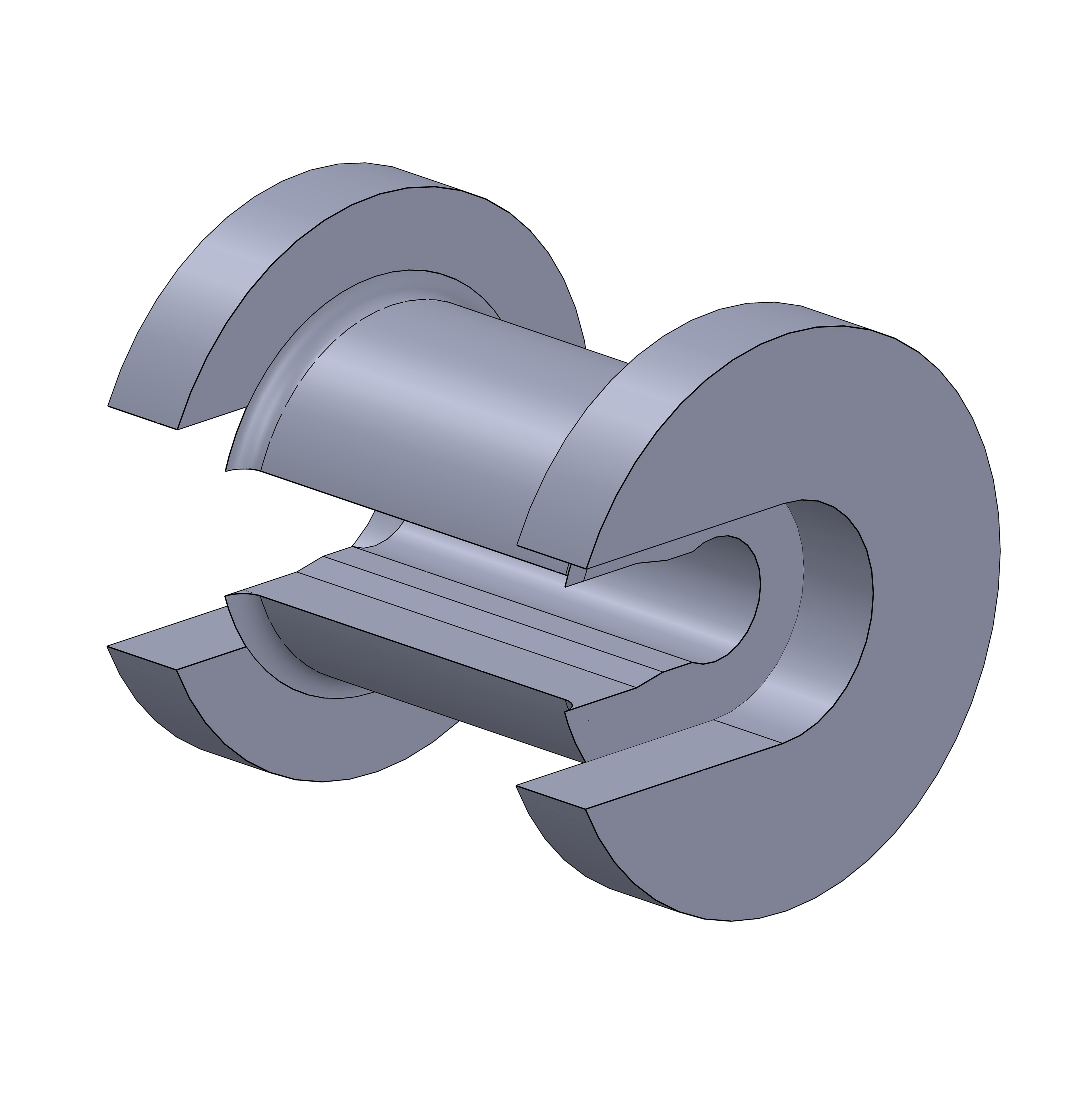
Exploded view of hook module
Actuation
Powered by LDO 217:1
Purpose 1: stows away to fit within 12”x12”x16” starting box
Purpose 2: lowest position slides directly underneath Oz Head hoop, can be actuated up to hook it
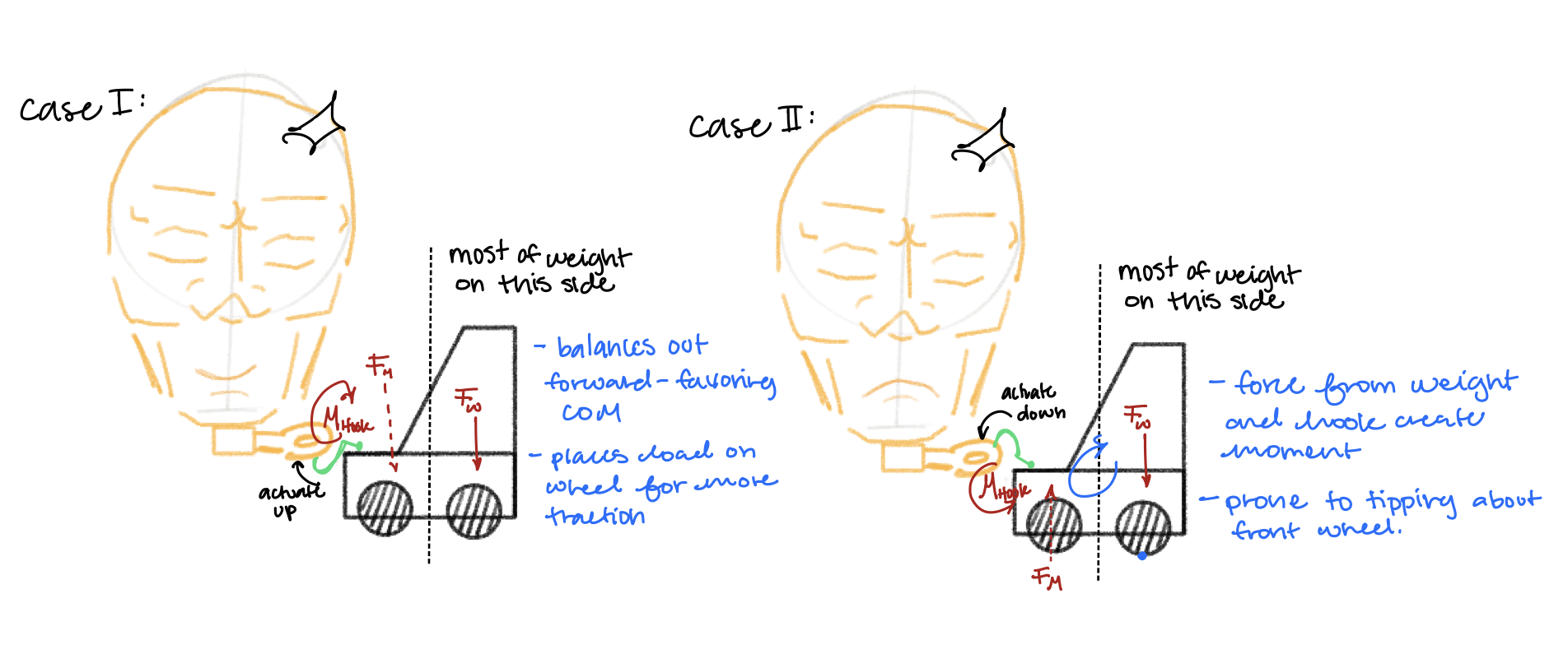
Purpose 3: intended mimic pushback tractor principle: place load over back wheel to prevent slippage. Because of that intention, it hooks upwards and uses highest torque LDO
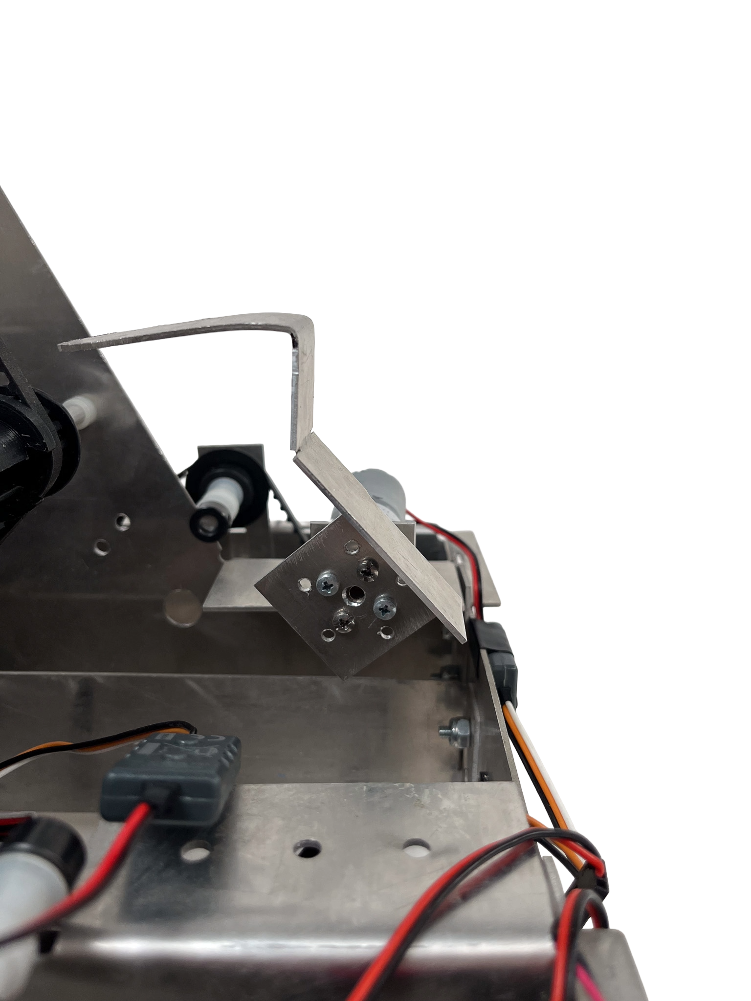
I. Stowed away
II. Actuating down/up
III. Lowest position
Design Process
Currently being updated... If you want to know more about my thoughts and considerations (and mistakes (and solutions to those mistakes)), calculations, and fabrication methods, check out design overview in slide format!
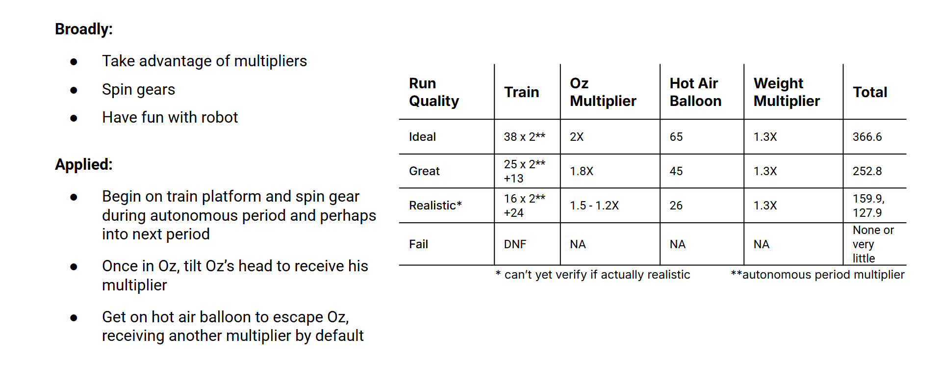
Strategy and Ideation
Our gameboard was themed after the movie Wicked and had many kinds of objectives and obstacles you could use to score points. I decided – though I did want to score lots of points – I wanted to prioritize having fun building my robot. With this in mind, I chose to go after the gear-driven train platform and hot air balloon to have an opportunity to explore gears and transmissions. Afterward, I conducted a strategy analysis to maximize my point potential with those objectives – leading me to include the Oz head multiplier.
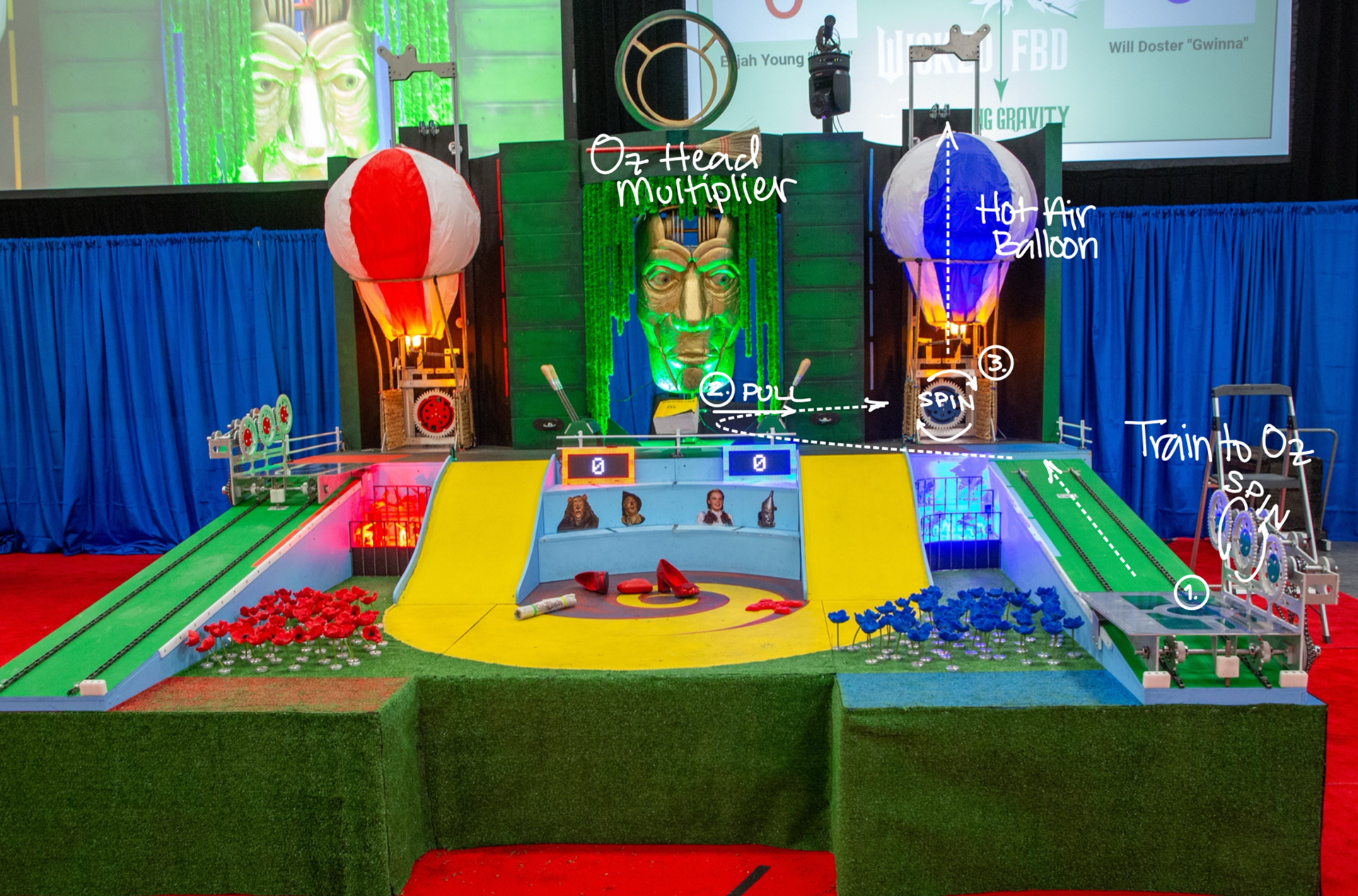
Our years gameboard notated with my planned strategy
Overview of Game/Build Constraints
- 2 min rounds
- 30s autonomous period
- 90s manual driving period
- must fit within 12"x12"x16"
- 12 lb. weight limit
- motor allowance of 4 servo and 4 LDO
- a maximum stored energy of 50kJ
- max battery voltage of 7.4V (LiPo)
Both the hot air balloon and train platforms would require my robot to spin geared platforms supporting the robots weight, which meant it would be beneficial to keep my robot light.
Additionally, completing the hot air balloon offered tiered point multipliers based on weight: 1.2x for 2-5 lbs., 1.3x for 5.1-8 lbs., and 1.4x for 8+ lbs. I decided on a goal weight of 5.1 lbs - the lowest weight necessary to fetch me the next multiplier tier. I judged that an 8+ load would increase the torque required to spin the gears too much, so anything above 5.1 lbs was effectively dead weight.
Another constraint was the issue that the hot air balloon and train platform gears were at different heights and spun in opposite directions; this would mean that my gear spinning mechanism would have to be able to move up and down, providing enough torque in both spinning directions.
Finally, I decided I would try to complete the Train to Oz obstacle within the 30 second autonomous period, since it would grant a 2x multiplier for points scored during the period. This would add a speed requirement to my gearbox, as well as require my robot to start through autonomous means (hands-free).
Progression to Minimum Viable Product
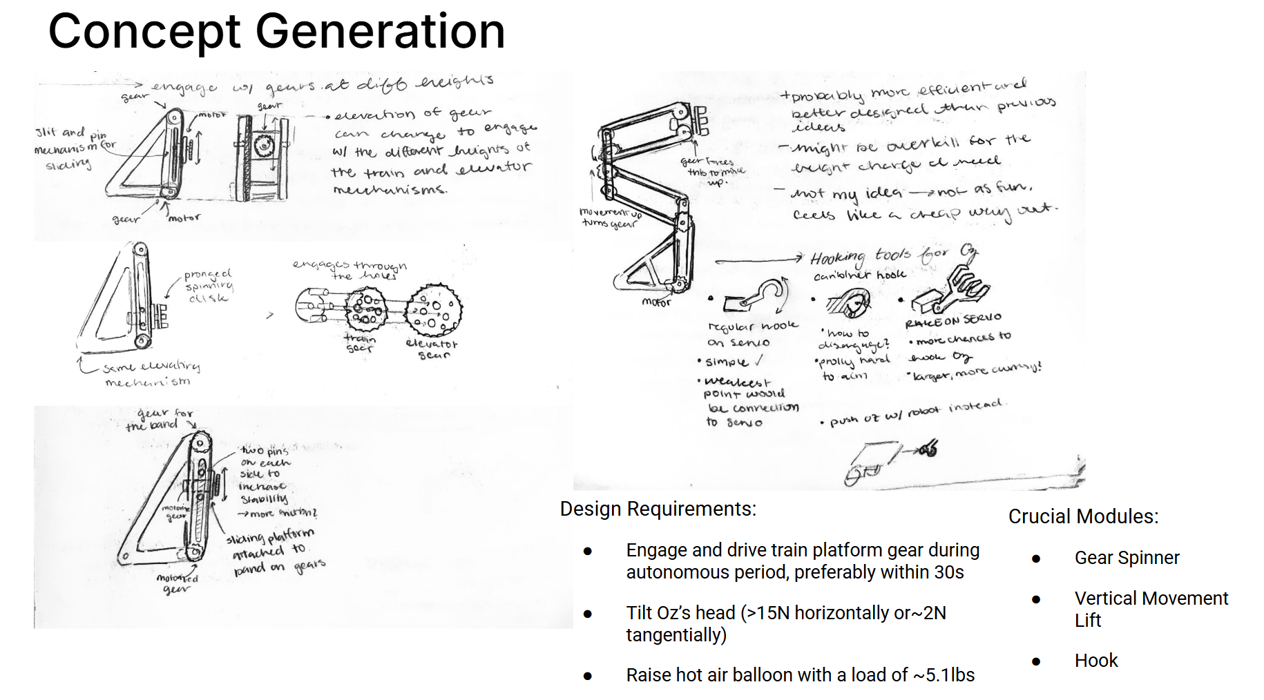
With my strategy decided, the first step to a minimum viable product -- the bare bones of a robot that could score points -- was to determine the most critical module (MCM) for my robot. Since my points would be scored by spinning the geared objectives on the gameboard, I decided my MCM would be a height-varying gear spinner.
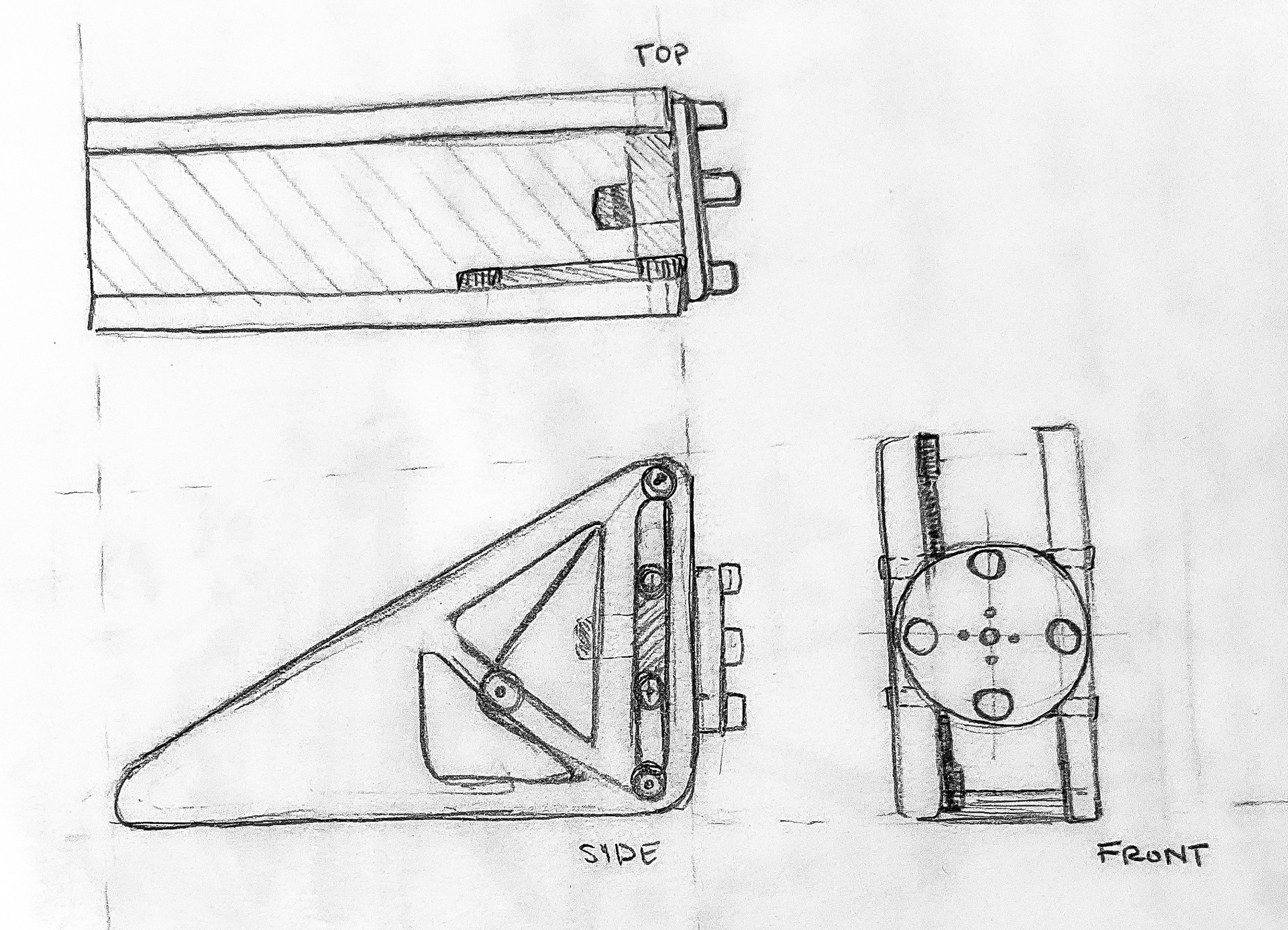
Early MCM Concept
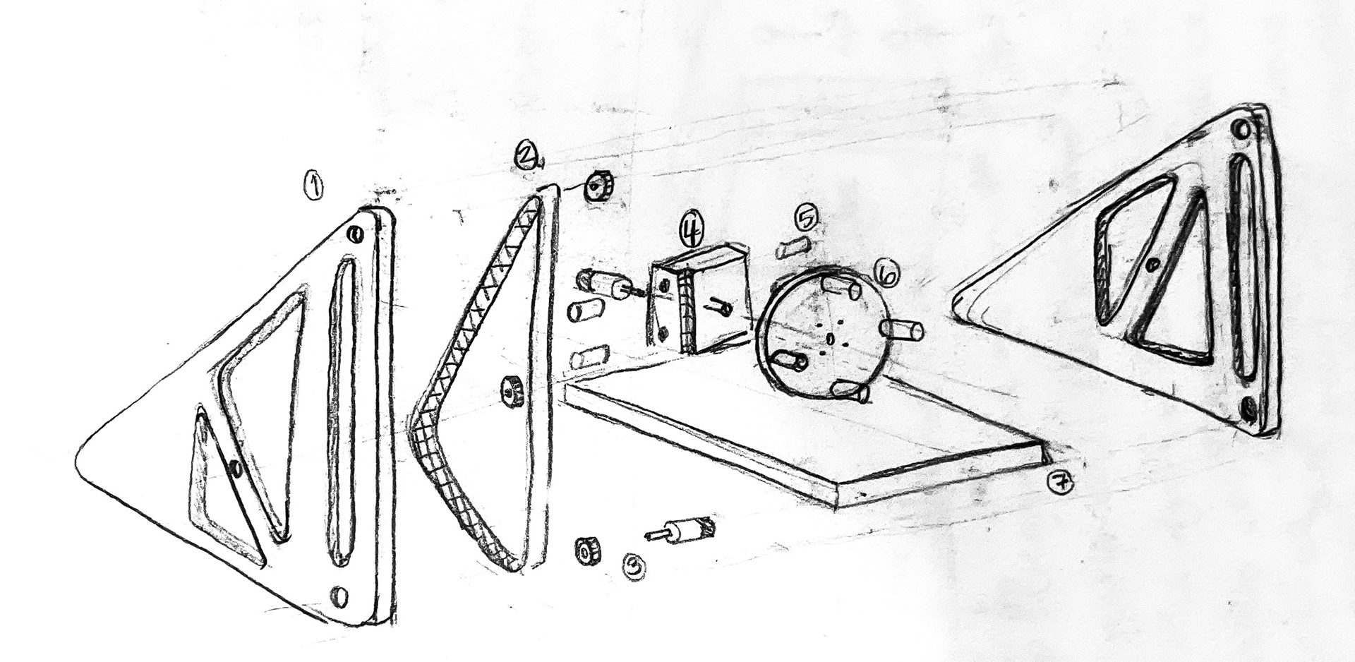
Early MCM (exploded)
The largest issue I encountered with the elevation mechanism was the large pool of options I could pursue, though I ultimately chose a belt-driven mechanism; since my goal was to move only a few inches pretty quickly, I opted against lead screws (typically slower), scissor lifts (high torque requirements early in movement), and four-bar linkages (overkill for needed travel distance). I had originally planned to constrain the gearbox-elevation mechanism using slots and pins, but I worried they would not be stiff enough to resist the pitch reaction force from spinning the gears.
After speaking to one of my lab instructors, I was introduced to a dovetail-shaped linear rails (thanks Kait!), which I chose to pursue because it both solved my original concerns and seemed fun to mill. I chose to use Delrin as material due to its low friction coefficient, and proceeded to mill it (yes, it was quite fun) with the guidance of Pappalardo shop staff (thanks Scott!).
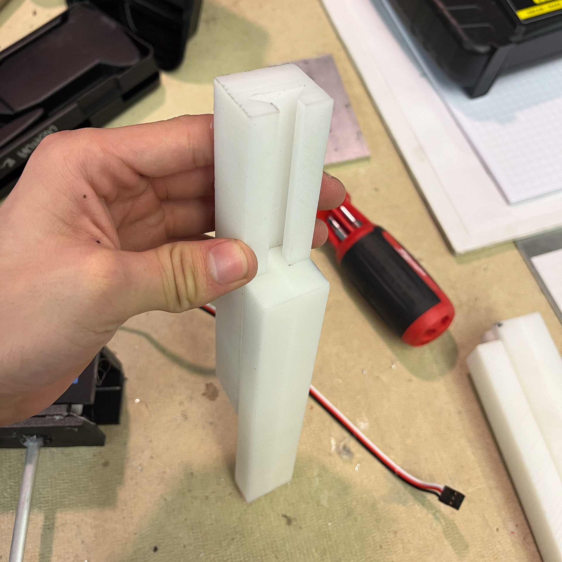
Dovetail slider
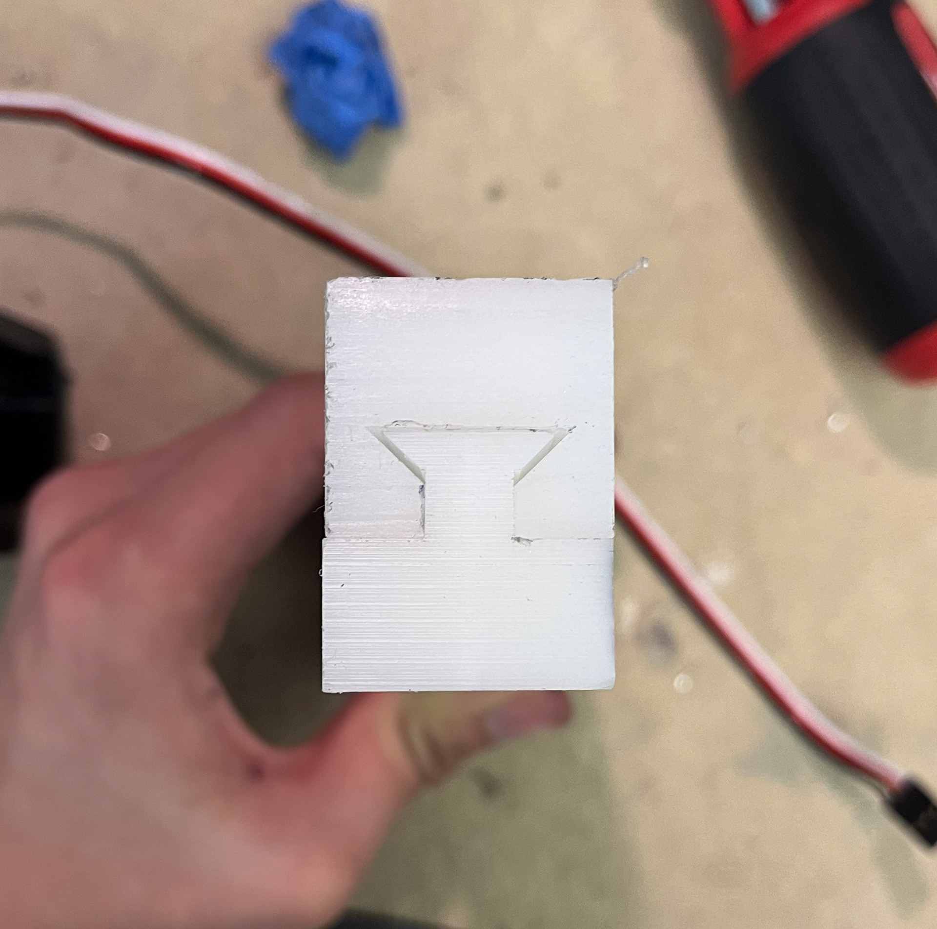
Dovetail slider again
I created my first gearbox version by measuring the force required to turn the gears with a force meter, then compared the available motors' torque speed curves to the required torque. This led me to a 2:1 gear ratio with a Bilda Torque servo motor. However, I would not realize until later that I had overlooked three major facts that would render this version essentially useless. Spoiler alert:
1. measured force required with no load -- my robot would not be massless
2. assumed a higher voltage than the stock batteries offered
3. did not account for rotation speed required to meet my sub-30s goal
Single-motor gearbox
Single-motor gearbox
Original gearbox-lift assem.
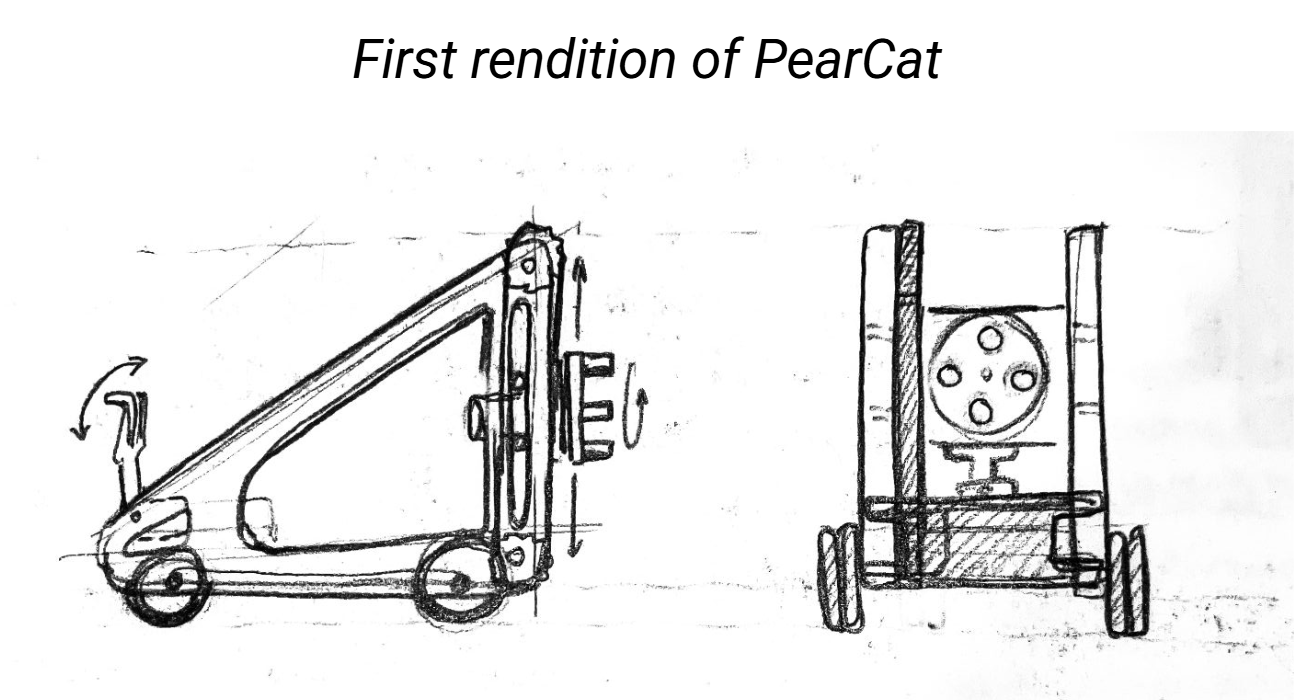
Without yet realizing the shortcomings of my gearbox, I combined it with my belt-drive elevator to complete the MCM and then shifted focused on the chassis for my minimum viable product. For my first iteration, I was only concerned about its ability to drive around, so I made the simplest effective body I could think of: a box.
Immediately after assembling with my MCM, I noticed that the chassis did not mesh well at all. The MCM was not stable when in motion -- as seen above -- so it would likely be unreliable when spinning the high-torque gears; furthermore, it made poor use of the space within the bounding box to support other modules I wanted to include (like all-wheel drive), which was unideal considering the volume constraint. Though less relevant for performance, I also thought it could look a lot cooler...
Chassis Redesign
My goal in the redesign was to reduce the compliance in the MCM due to the chassis, eliminate redundant aluminum to keep weight as low as possible, and in general offer a more elegant incorporation for my MCM and future all-wheel drive and hook modules. The pieces were waterjet to eliminate as much misalignment as possible (thanks Bill!).
Gearbox Design Shortfalls
After assembling my full bot with the revised chassis, I conducted my first full Train to Oz trial... which failed. The original gearbox design, which included a single motor at 2:1 gear reduction, stalled at the easiest gear.
I quickly mocked up a 3:1 ratio gearbox thinking it just need a some more power to account for real life inefficiencies, though even this was far too weak -- taking 50 - 60s to drive the Train to Oz at the lowest torque. Not only was it wayyyy too slow to complete during the autonomous period, but it also left incredibly little time for the Oz Head multiplier and the Hot Air balloon obstacle -- which required even more torque than the Train to Oz...
After carefully redoing my calculations, I realized I had made a series of mistakes -- the same which I divulged earlier -- due to jumping the gun under pressure to build quickly:
1. Forgot to Account for Load
- I tested the force required to spin the gears... but without any load on the platform. With a robot mass of ~2.5kg, I was shooting for a much lower required torque than actually necessary.
2. Wrongfully Assumed Higher Battery Voltage
- I had calculated the motor/gear ratio fit assuming our battery packs fed 6V, while reality was closer to 4.8V. A lower voltage meant a lower torque-speed curve.
3. Didn't Consider Motor Speed Requirement
- I failed to consider the required motor speed to finish the Train to Oz in 30s. Even if I had correctly calculated the torque requirement, the gearbox would have not been fast enough to meet the goal.
These mistakes led to a big knot of confusion which can be somewhat summed up with the below diagram:
Despite realizing this, I had to prioritize finishing the rest of robot instead of redesigning my gearbox. I had already spent a lot of time on the chassis redesign, leaving me with only 3 weeks before impounding deadline and lots of other pending modules to work on: drivetrain, hooking mechanism, autonomous start and programming, and driving/troubleshooting.
The blunder of redesigning my chassis before testing my gearbox taught me the value of prioritizing the hard way. Since it was technically capable of scoring points on the train obstacle (albeit poorly), I had to focus on finishing the rest of my fabrication plans. Conversely, I could not drag out any of the remaining modules if I wanted any chance to improve my gearbox (spoiler again: I did -- continue below if you are curious as to how).
Speed Running: Drivetrain and Tow Hook
Though I originally had dreams of interesting and complex mechanisms for all modules of my bot, I had to make peace with the harsh reality of an impending deadline. For that reason I pushed to keep my drivetrain and hooking modules as simple as was still effective -- particularly aiming for low fabrication times
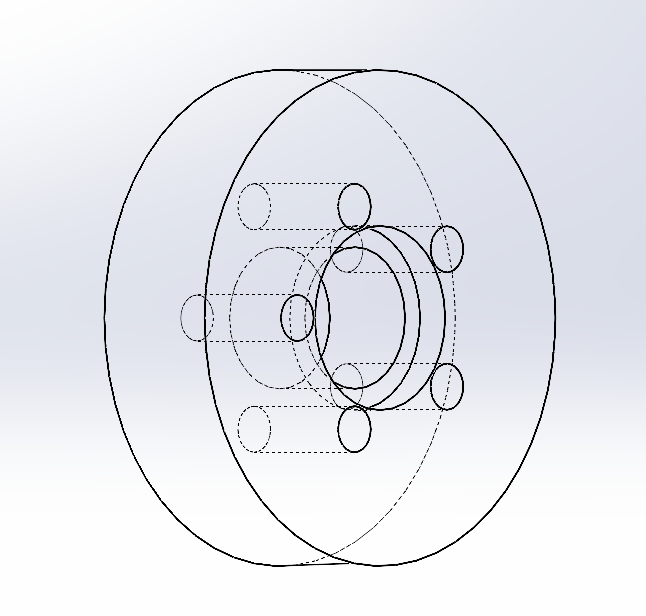
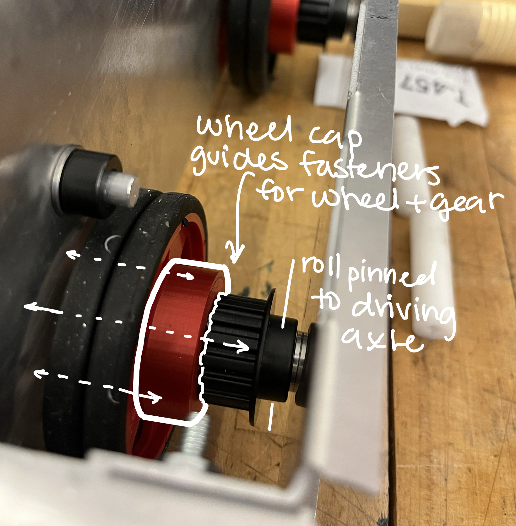
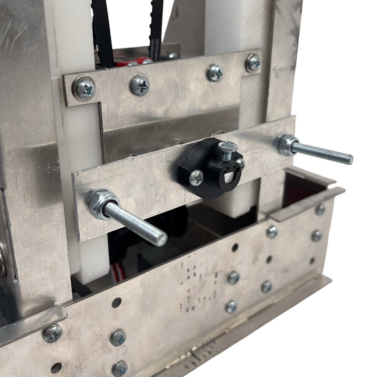
For my drivetrain, I used timing belts and gears to make an all-wheel drive. I designed and printed wheel caps that saved a lot of time fastening the gears to the wheels.
To tension the wheels, I cut A-shaped aluminum pieces -- a rectangle with a hole for the bearing and a slot below; these allowed me to manually tension the belt by sliding the A-slides up or down, avoiding the hassle of more time-intensive solutions like cutting and rejoining the belt, spring-loaded tensioner, or calculating the the ideal axle placements and re-cutting the chassis.
A measured force of 15N was required to fully turn the Oz Head multiplier. To ensure my robot would have enough traction, I wanted to mimic a design principle of a pushback tractor: leveraging a heavy load directly over wheels in order to prevent slipping.
I found an upward hook actuation served this purpose best, with the rest of the design being driven by simplicity of fabrication to save time for gearbox redesign.

Gearbox Redesign: Calculations
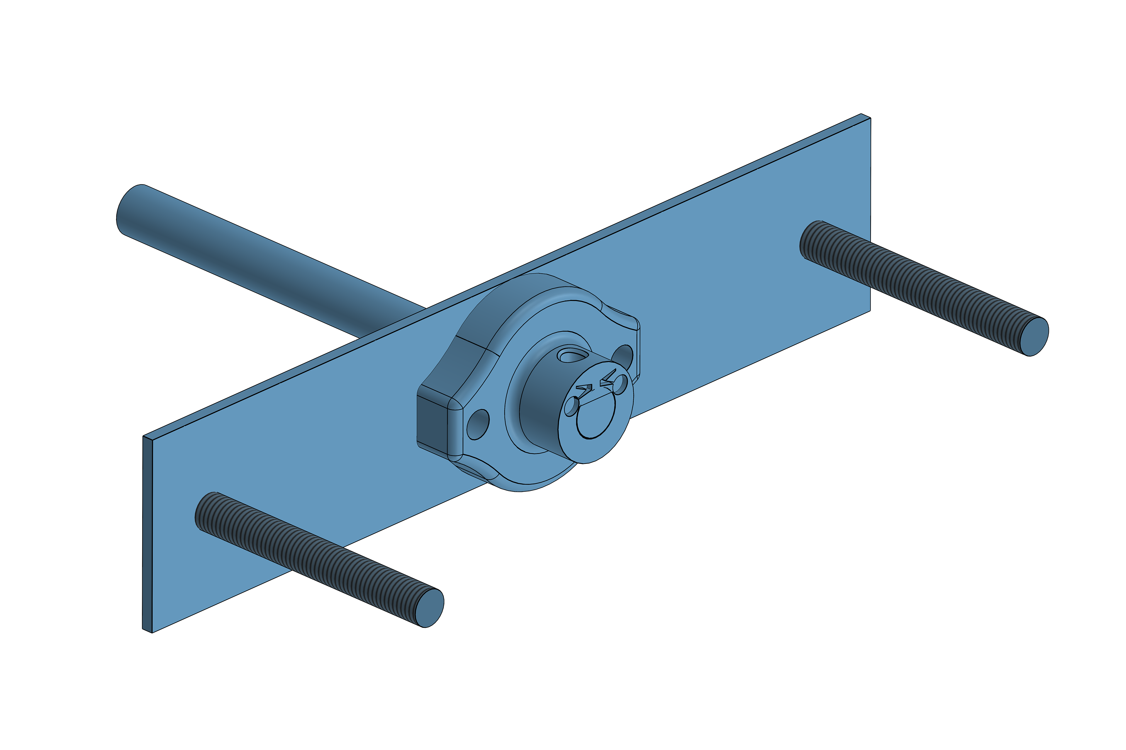
CAD of snap-on belt spacer

Cad of snap-on belt spacer (side profile)
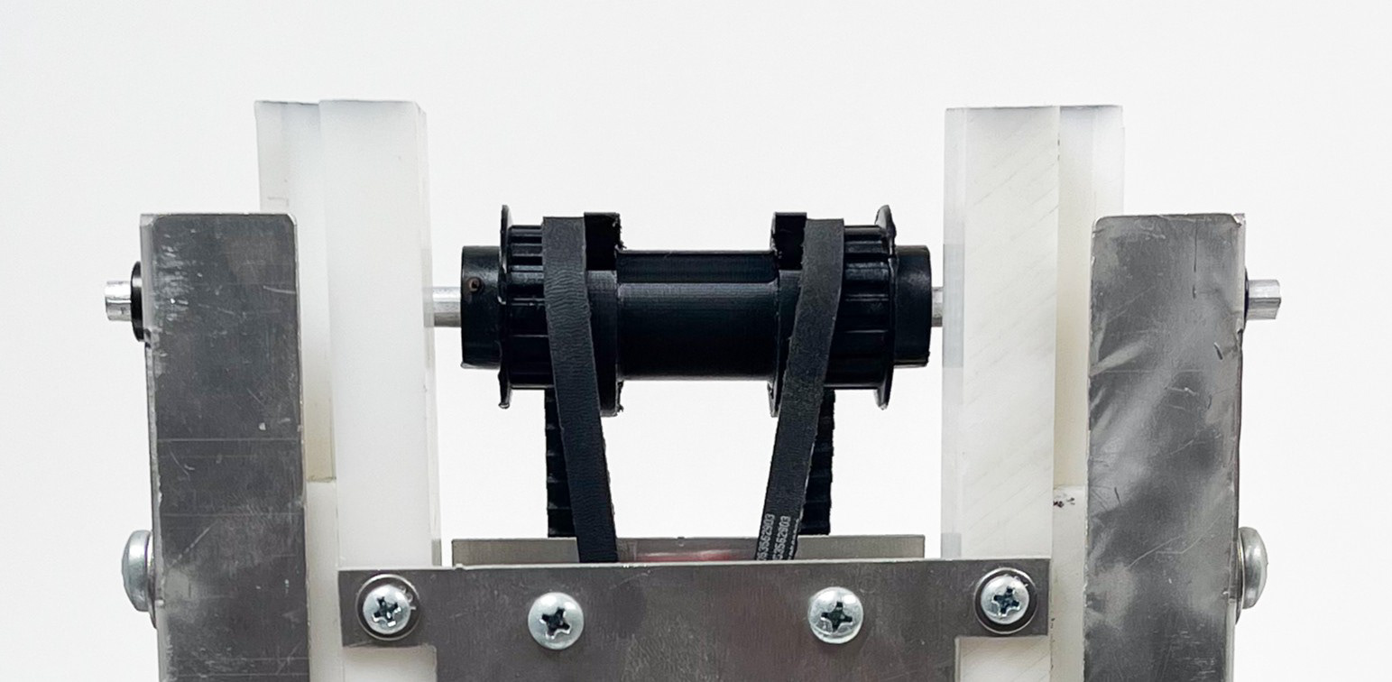
Spacer on PearCat
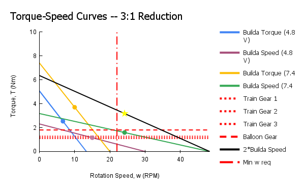
Different motors' torque-speed curves (solid lines) against the torque and rotation speed requirements (dotted in red)
During the overhaul, I realized that the new issue would be space, since I was constrained to bounding box I had originally intended for a single motor. The timing belt clamps ended up taking the brunt of the redesign, shifting inwards and growing shafts to double as spacers. Though, this new alignment caused the belts to become slightly crooked, the spacers I had already made did a good enough job at keeping them from slipping off.
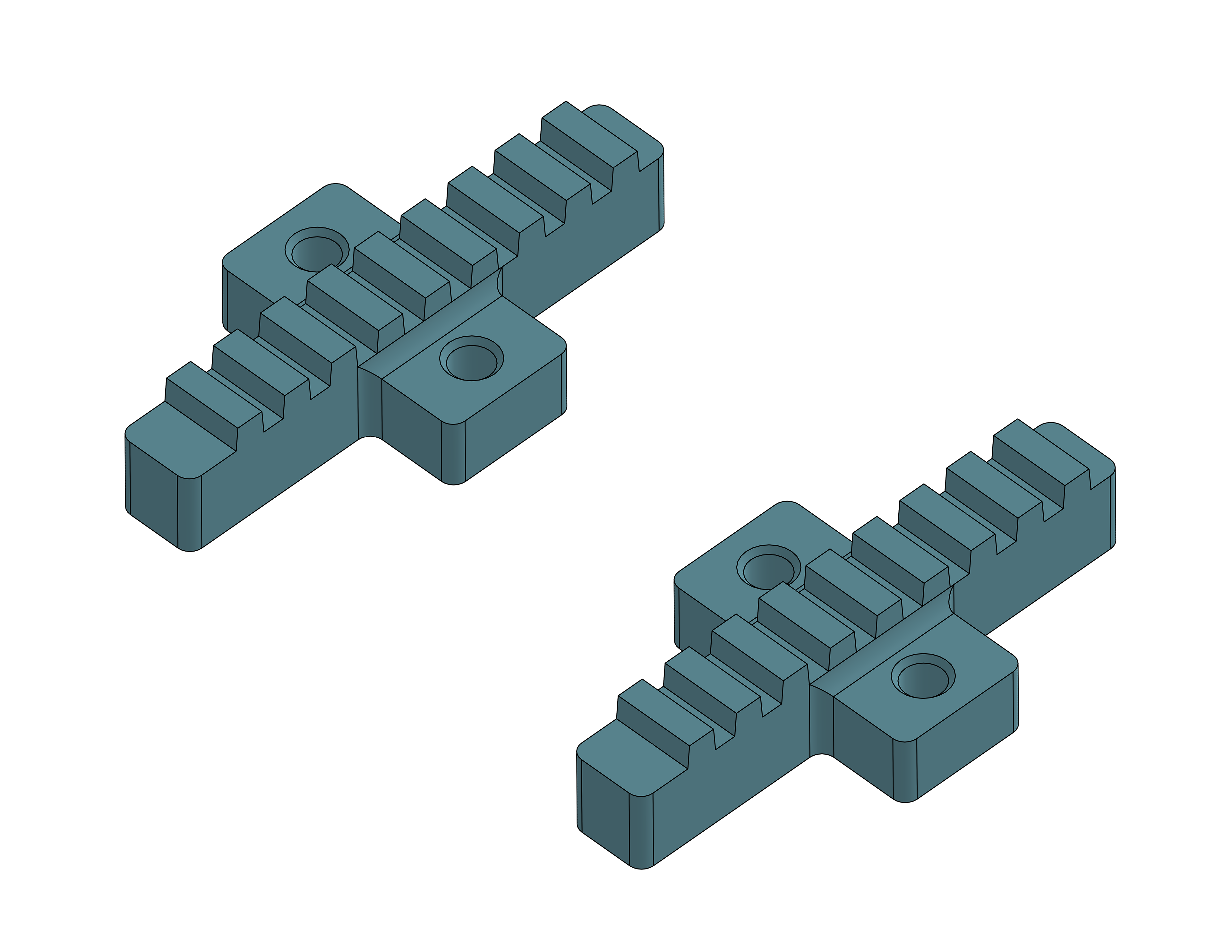
Original Belt Clamps
Final Belt Clamps
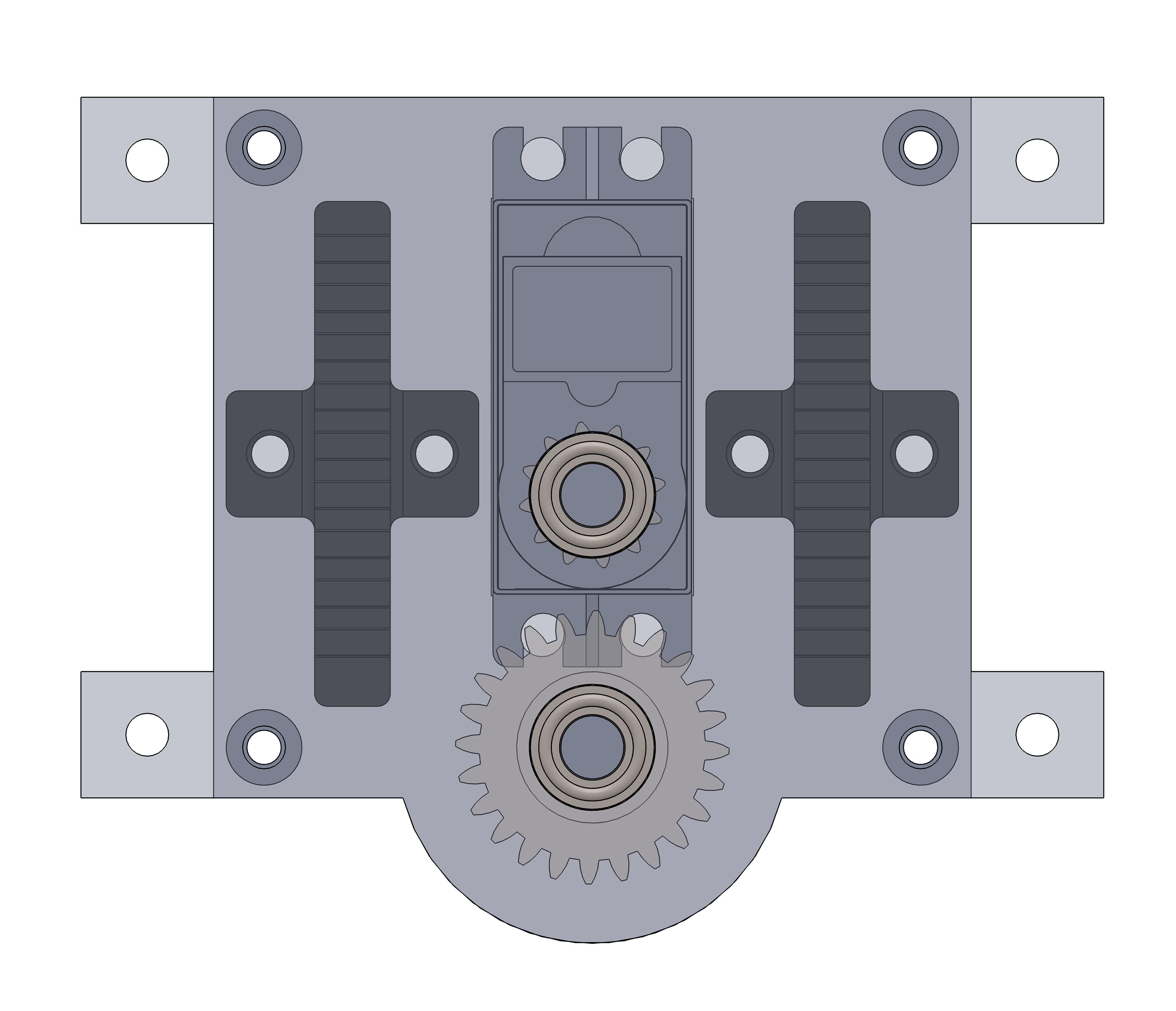
Single motor gearbox layout
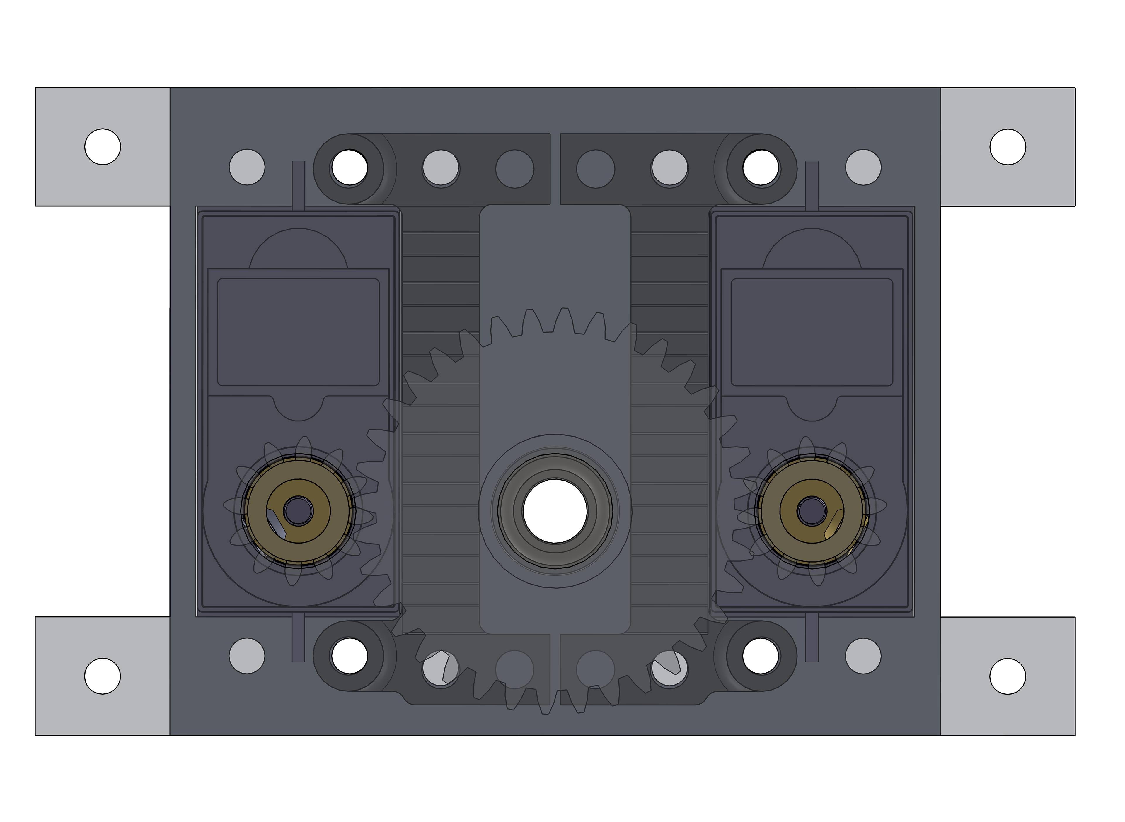
Two-motor gear box layout
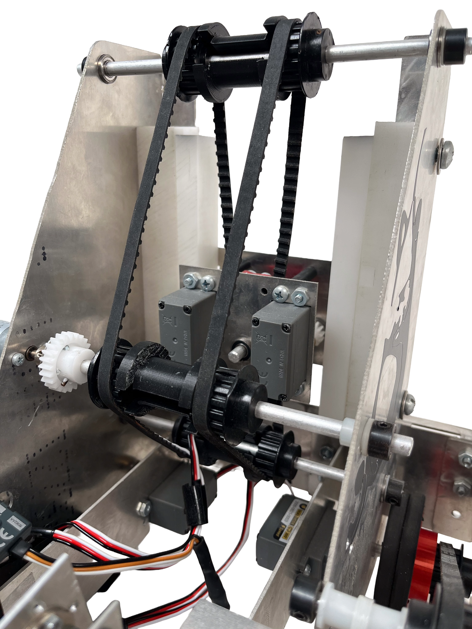
As I implied before, the design overhaul was really effective. The original, single-motor gearbox took around 50s-60s to complete the Train to Oz objective, while the final two-motor gearbox took from 19s-24s -- a 2x improvement at worst and over 3x at best. See the video below for a direct comparison of both in action:
Original single-motor gear spinner (left) vs final two-motor version (right)
The final change I had to make to the gear-spinning mechanism came after the two-motor redesign. My new gearbox had enough torque that the set screw holding the gear-spinner claw would slip on the shaft; I once again consulted one of my lab instructors, who recommended filing the shaft down into a D-shaft. I designed and 3D-printed an accompanying adaptor.
Gear-spinning claw assembly