- Experiment Design
- Data Analysis
- Technical Communication
- SOLIDWORKS
- FDM 3D Printing
- MATLAB
- Excel
- Adobe Illustrator
- Instron/ADMET Universal Testing Machine
My research on the performance of 3D-printed beams was conducted for 2.671: Measurement and Instrumentation. Through the semester, the class exposes students to various testing and data analysis instruments, techniques, and programs through labs and post labs; simultaneously, students are tasked with ideating a research topic, conducting a literary review, designing the experimental set-up, executing the experiment, analyzing the data, and interpreting the results -- culminating in a class flash talk, poster session, and final research paper. If you are interested in my procedure and results, I recommend viewing my poster or reading my paper, both linked immediately below.
Flash Talk
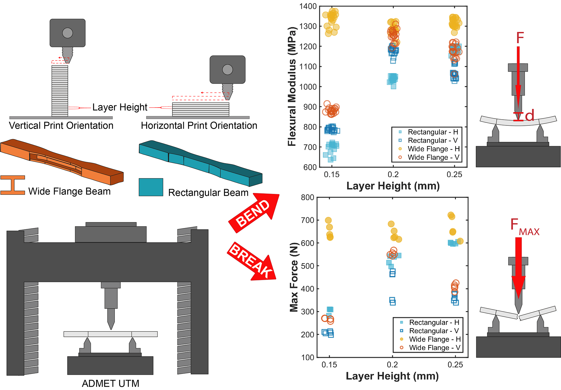
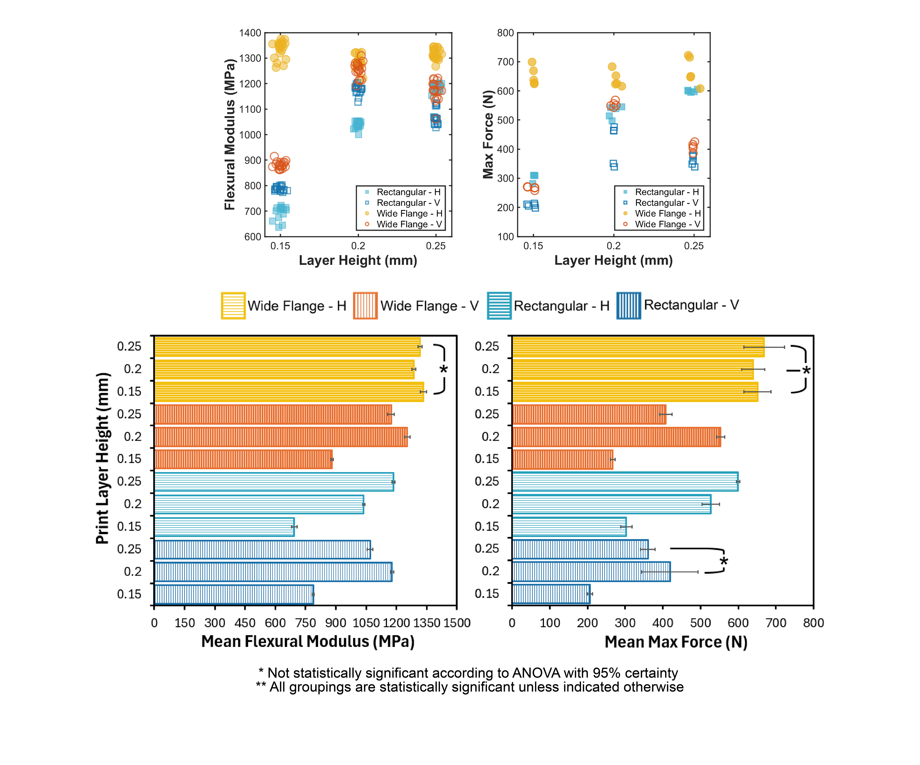
3D printing is now everywhere – from industry to schools to homes – and people are increasingly using printed parts in load-bearing applications. Yet, most of what we know about their mechanical behavior come from research using standardized testing samples, excluding lots of geometries people are actually printing. To help bridge this gap, I tested two beam shapes: a rectangular beam following ASTM testing standards and a wide flange beam designed to have an equivalent bending moment of inertia. I printed each horizontally and vertically, and at three different layer heights. I tested them in three point bending to find their flexural modulus and maximum load capacity before failure. Overall, wide flange beams outperformed rectangular beams, as expected. However, each geometry had a distinct relationship with print orientation and layer height, suggesting that trends found from standardized testing samples may not generalizable to other printed shapes.