- Machine Design
- Movement System Parametrization
- SOLIDWORKS
- Python
- Google Sheets
- FDM 3D Printing
- Laser Cutting
The Cantilevered DeltaXY is a movement system engineered for unusually high lateral space efficiency — wide enough to reach beyond its own footprint. As an undergraduate researcher in MIT's Ideation Laboratory, I worked directly under its designer, Ilan Moyer, to improve the architecture's accuracy. This work contributed to a paper published at ACM CHI 2026, which received the conference's Best Paper Award.
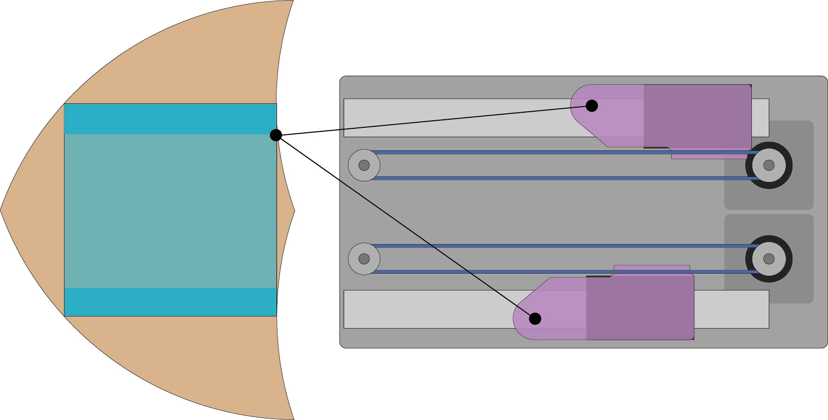
Diagram of Cantilevered DeltaXY on the FabUnit (right) and the range of the toolhead (left). Image courtesy of Ilan Moyer
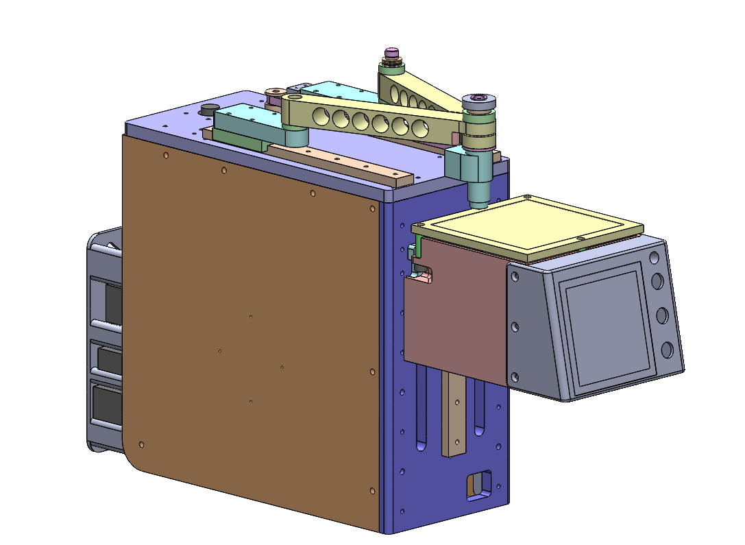
CAD of the FabUnit printer. Image courtesy of Ilan Moyer
Over my sophomore summer, I began working as an undergraduate researcher in MIT's Ideation Laboratory. My research was focused on the Cantilevered DeltaXY architecture - a movement system with high lateral-space efficiency (LSE) designed by Ilan Moyer during the creation of the his ultra-thin 3D printer, FabUnit. The FabUnit The high LSE from Cantilevered DeltaXY gave the 3D printer a uniquely wide reach despite its narrow frame - wide enough to reach past the bounds of its print plate.
Working directly under Ilan, my early research focused on aiding in increasing the accuracy of a 3D printer using the movement system by parametrizing possible kinematics. Afterwards, my focus shifted on implementing the architecture into a more-easily prototype-able form that could be used to explore other uses for its wide reach, namely collaboration between multiple machines with the same movement system.
I. Optimizing Accuracy
Parameterizing Kinematics
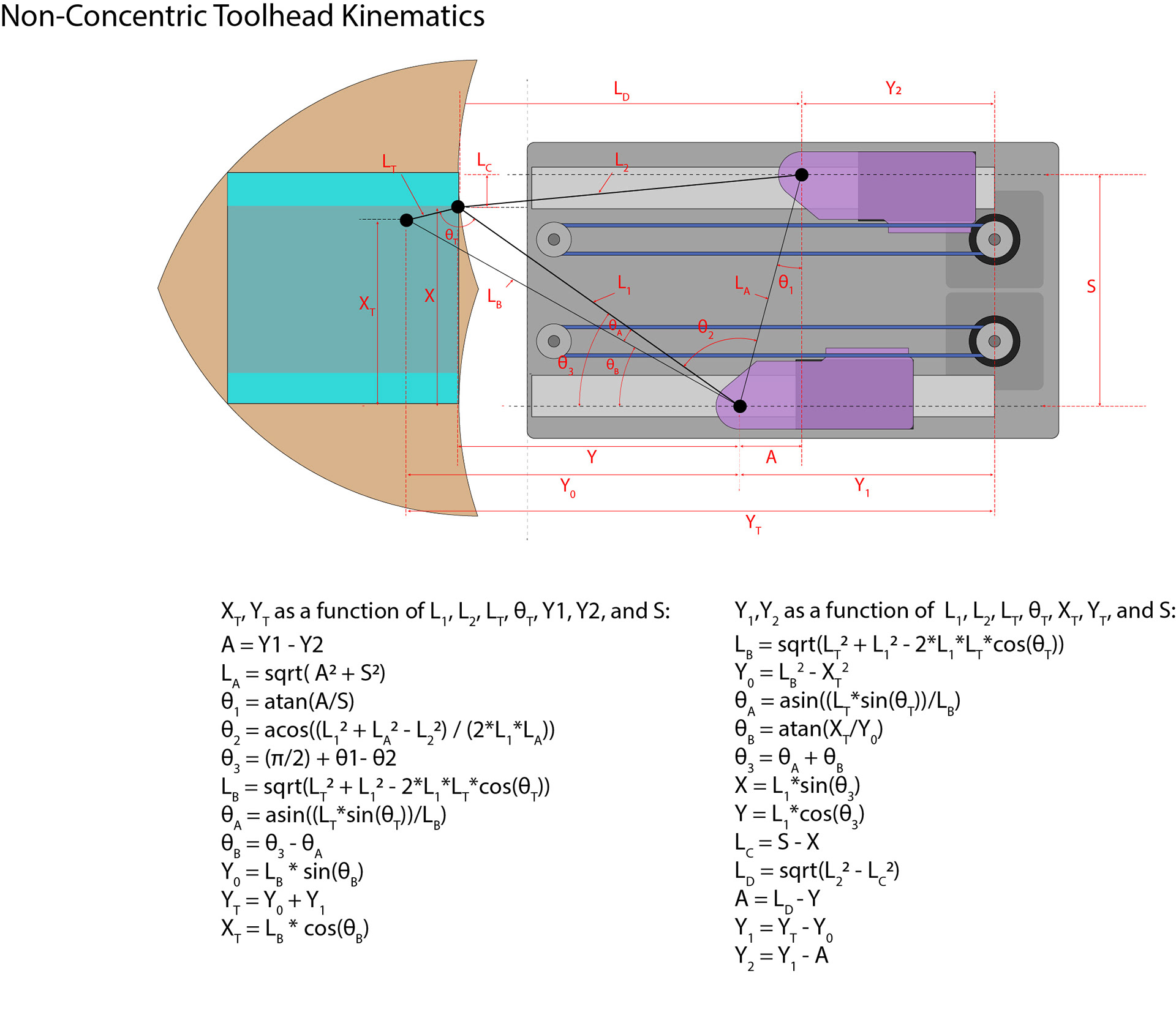
The files 3D-printed from the FabUnit were slightly inaccurate, typically skewed in one direction. There multiple theories for the underlying cause, though it was decided that the most likely was that the printhead was not perfectly concentric. To increase the accuracy, we collaborated with Quentin Bolsee - a post-doc for the Center of Bits of Atoms at MIT's Media Lab. I was tasked with parametrizing the Cantilevered DeltaXY forward and reverse kinematics in a case where a toolhead was not perfectly concentric. Forward kinematics involved calculating the position of the toolhead given the motor position, while reverse kinematics calculated the motor positions from the toolhead coordinates:
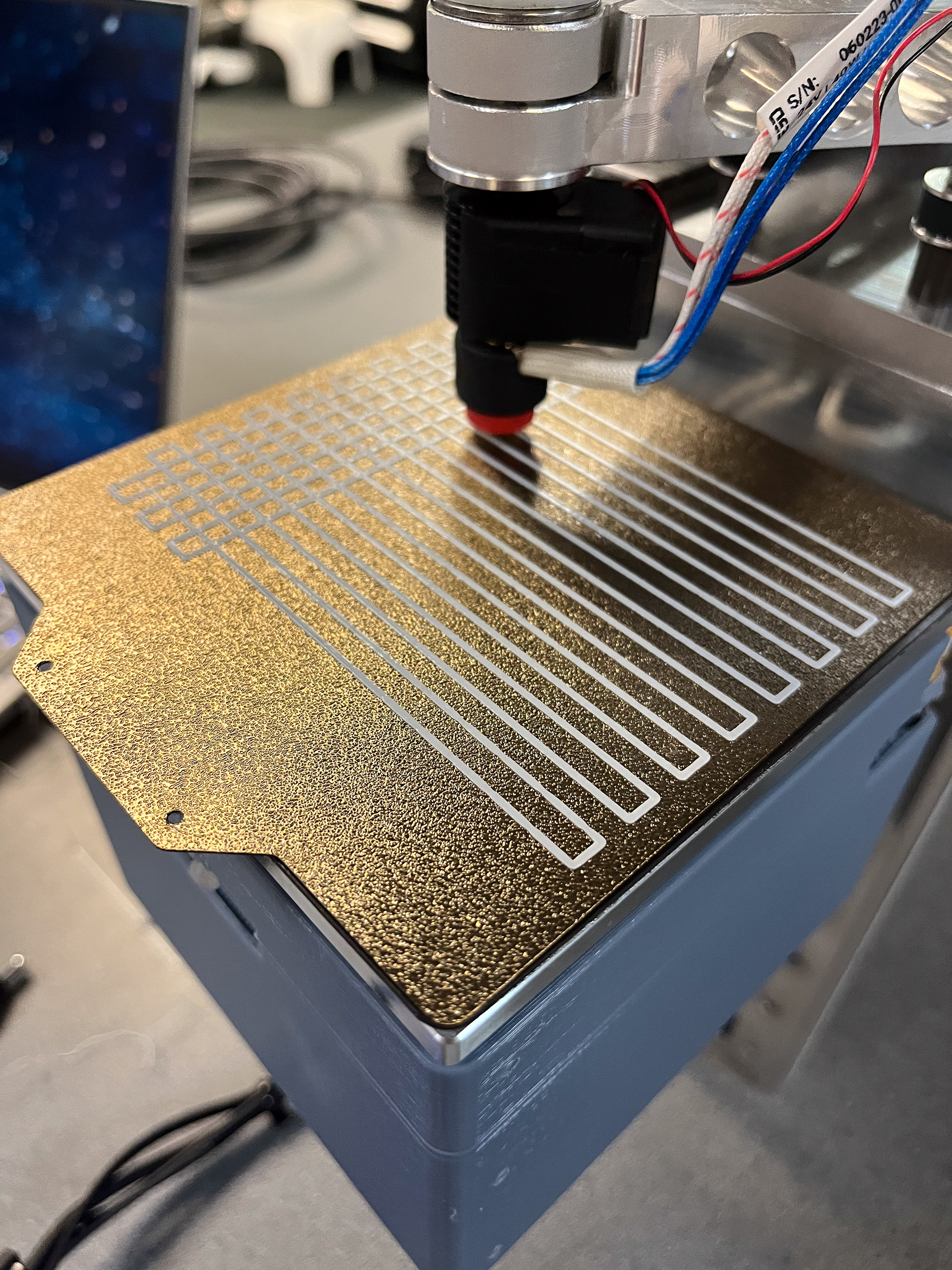
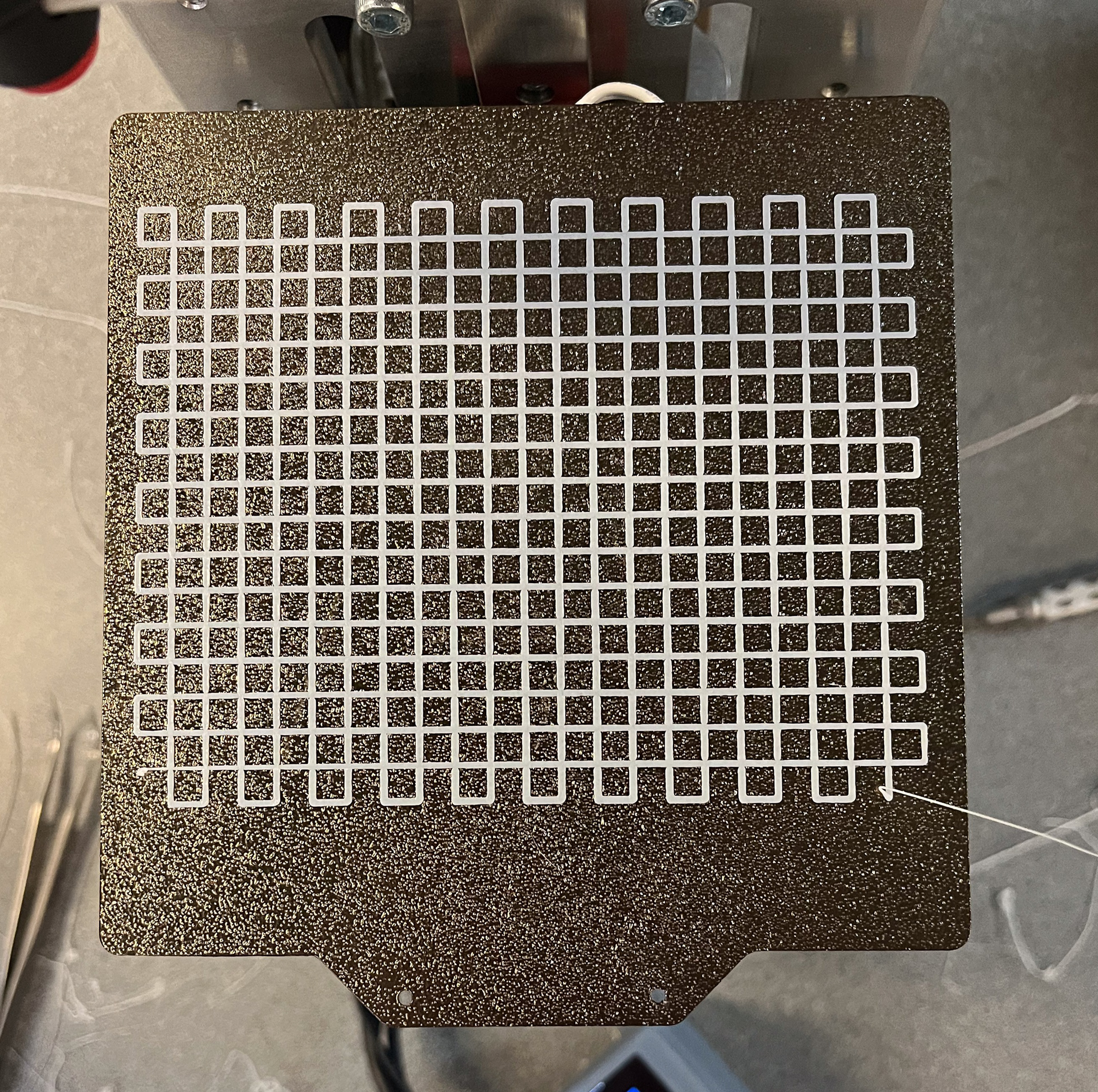
While collaborating with Quentin, I wrote Python scripts verify the kinematics I derived and introduce the JAX library to ease the integration with Quentin's computer vision further down the line. Next, I wrote a G-Code script for a grid-shaped 3D print test piece. Using computer vision, Quentin could assign coordinates to the intersection points of the grid and compare the actual coordinates to the hypothetical coordinates computed with my derived kinematics.
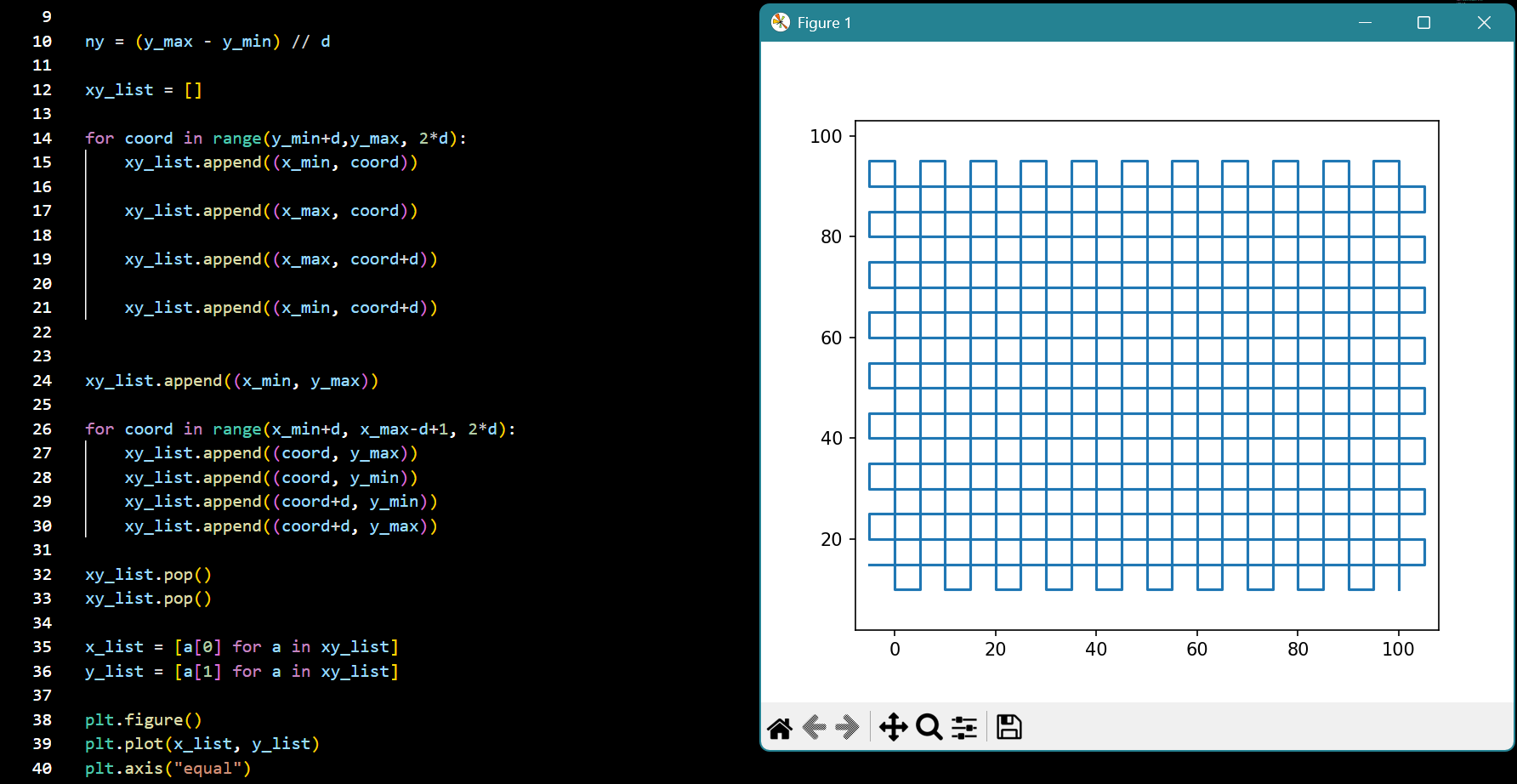
Code snippet from G-Code generating script
II. Building Prototype-able Form Factor
High-fidelity Prototype
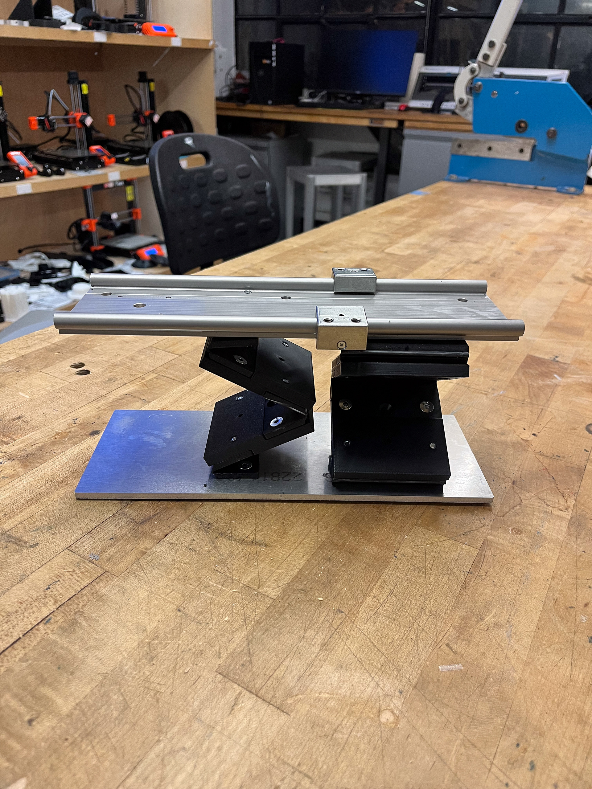
An important design principle behind the Cantilevered DeltaXY architecture is the narrow, unobtrusive width. It was clear to us that the same should be true when moving forward to a new form factor. When ideating a machine that could collaborate with others of its kind, it also made most sense to keep the work platform at the same level and instead actuate the movement system in the z-axis. Another important design consideration was that the z-level should be easily trackable at all times to keep the machine kinematics from becoming unnecessarily more complicated. All of these led us to a paired Sarrus linkage driven by a non-captive lead screw; when paired, the Sarrus linkages ensure both top and bottom planes remain parallel, while a lead screw provides dependable translation.
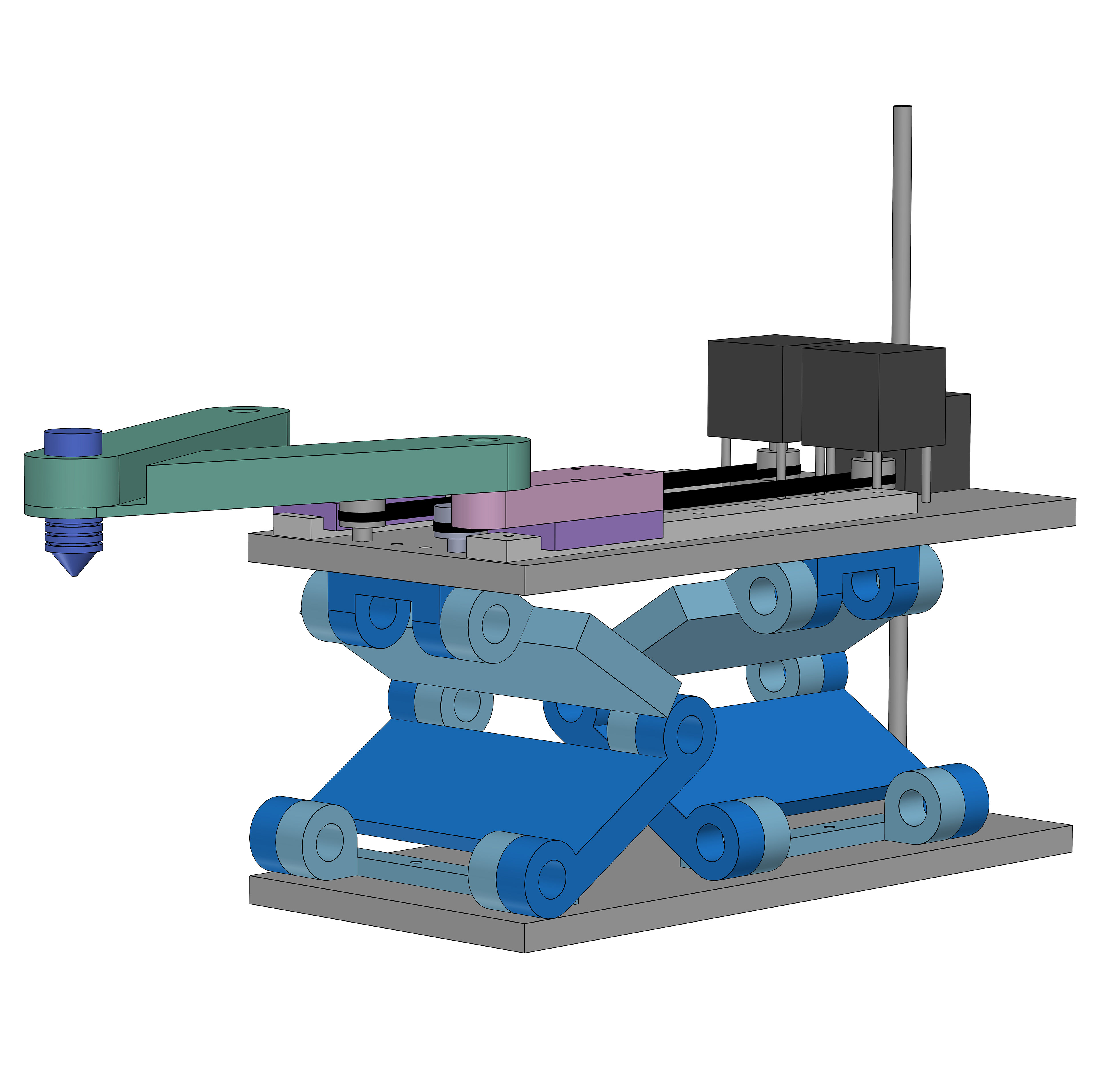
Early CAD concept for a fully collapsible Sarrus linkage and non-captive lead screw design
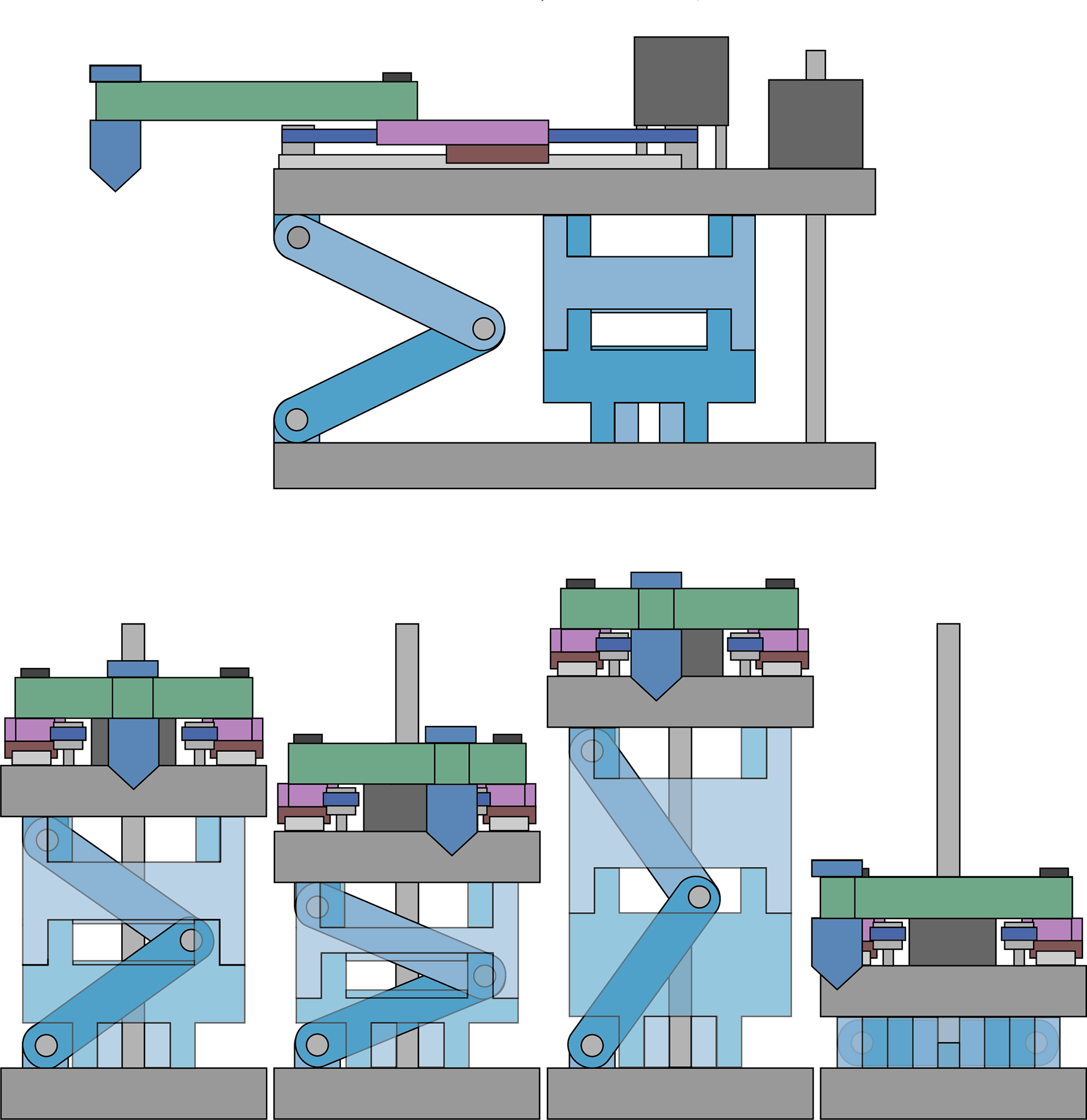
Elevation view and depiction of multiple machines side-by-side
To further investigate and motivate the design of the Sarrus linkages, I calculated the compliances of various linkage-bearing combinations and designs, ultimately landing on one with equally spaced upper and lower bearing shoulders since it was nearly 3x stiffer than the original design seen above.
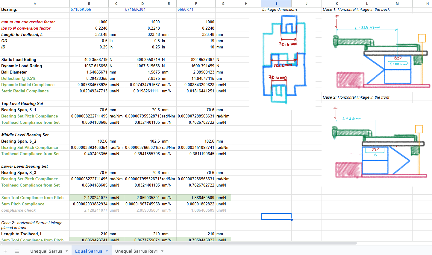
Snippet of compliance calculation sheet
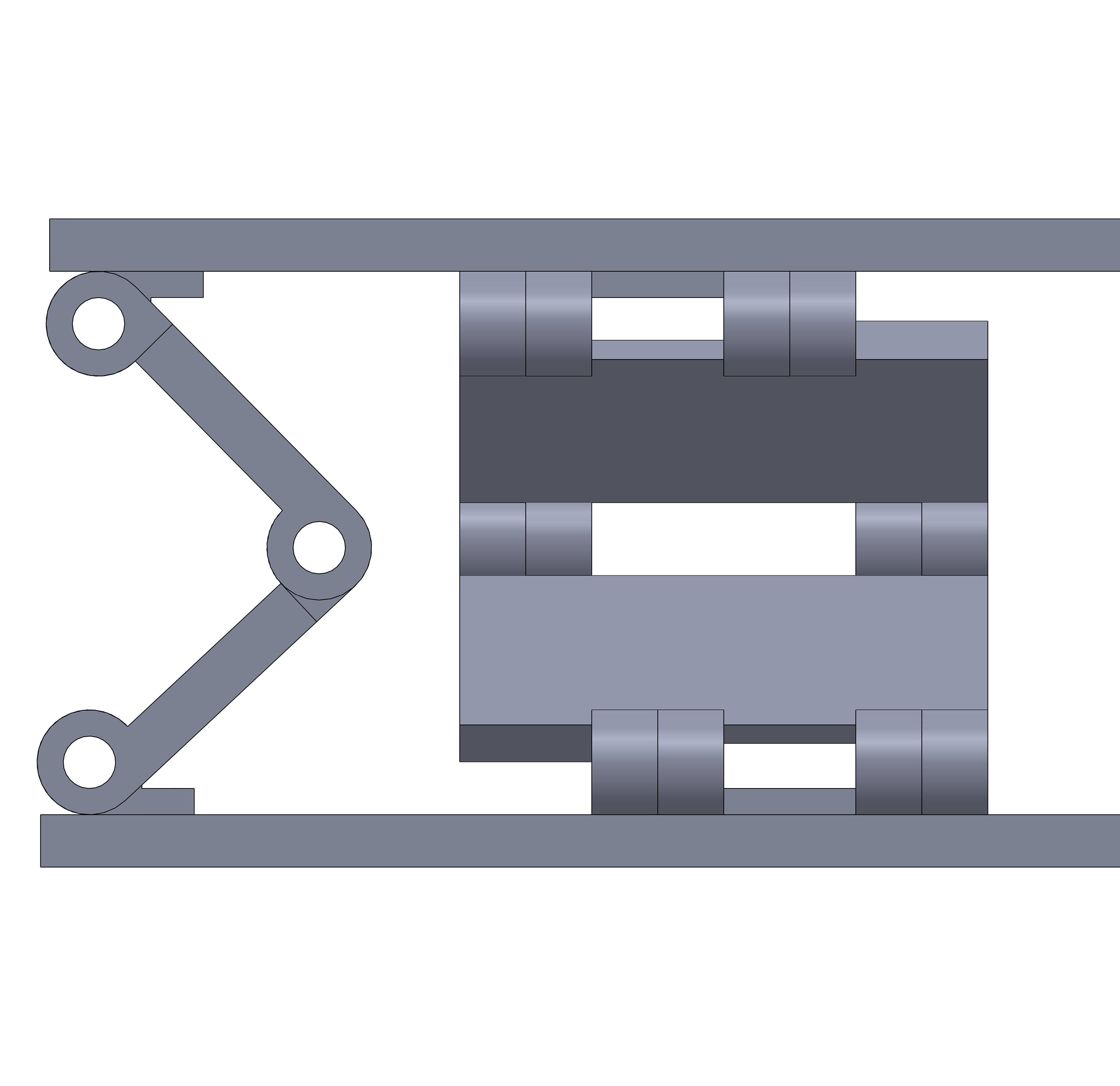
Equally-spaced Sarrus linkage
Design and fabrication of the high-fidelity prototype still in progress...
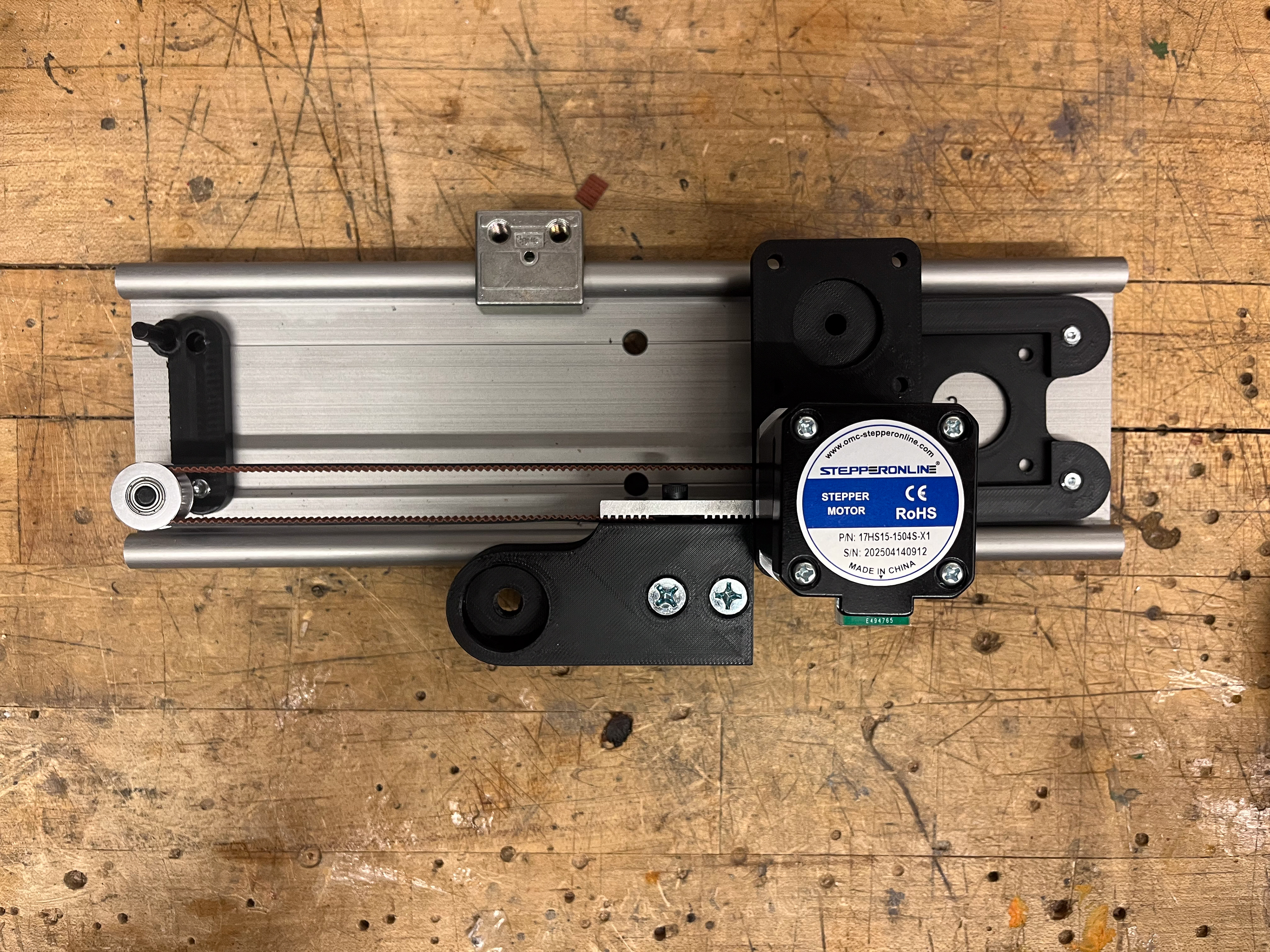
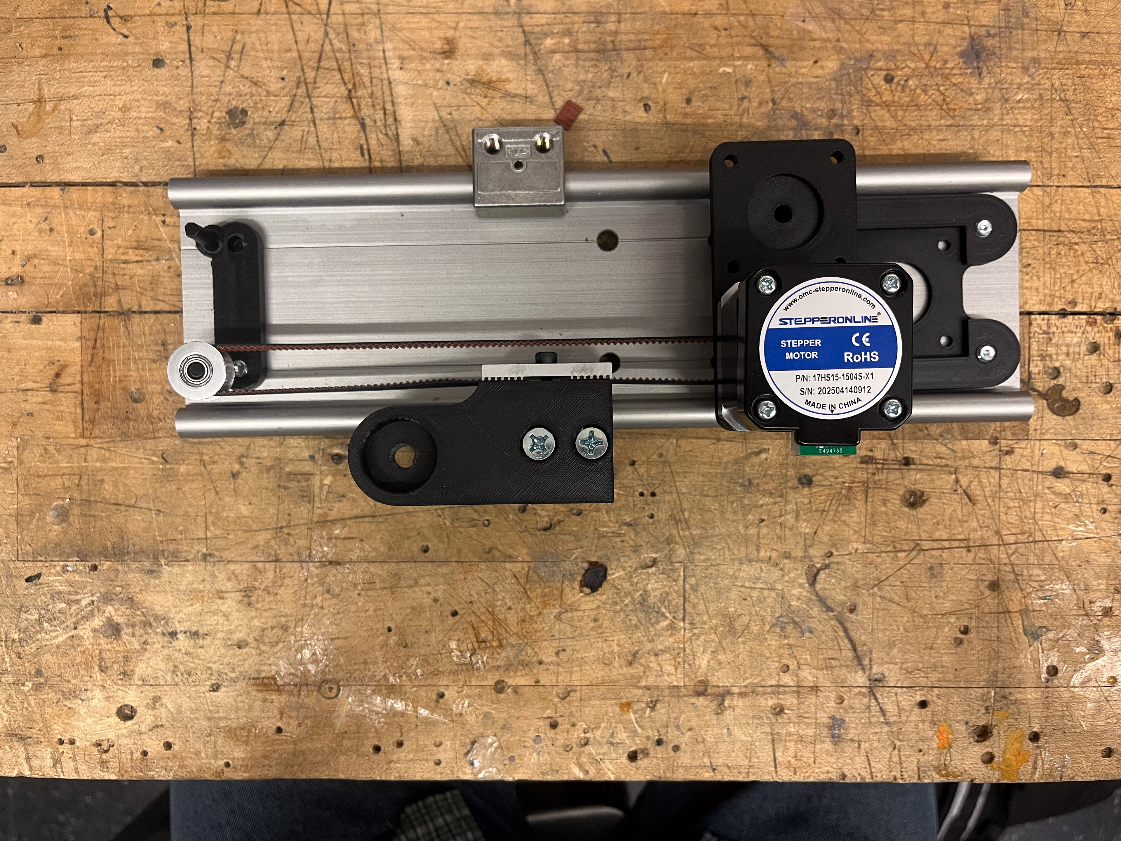
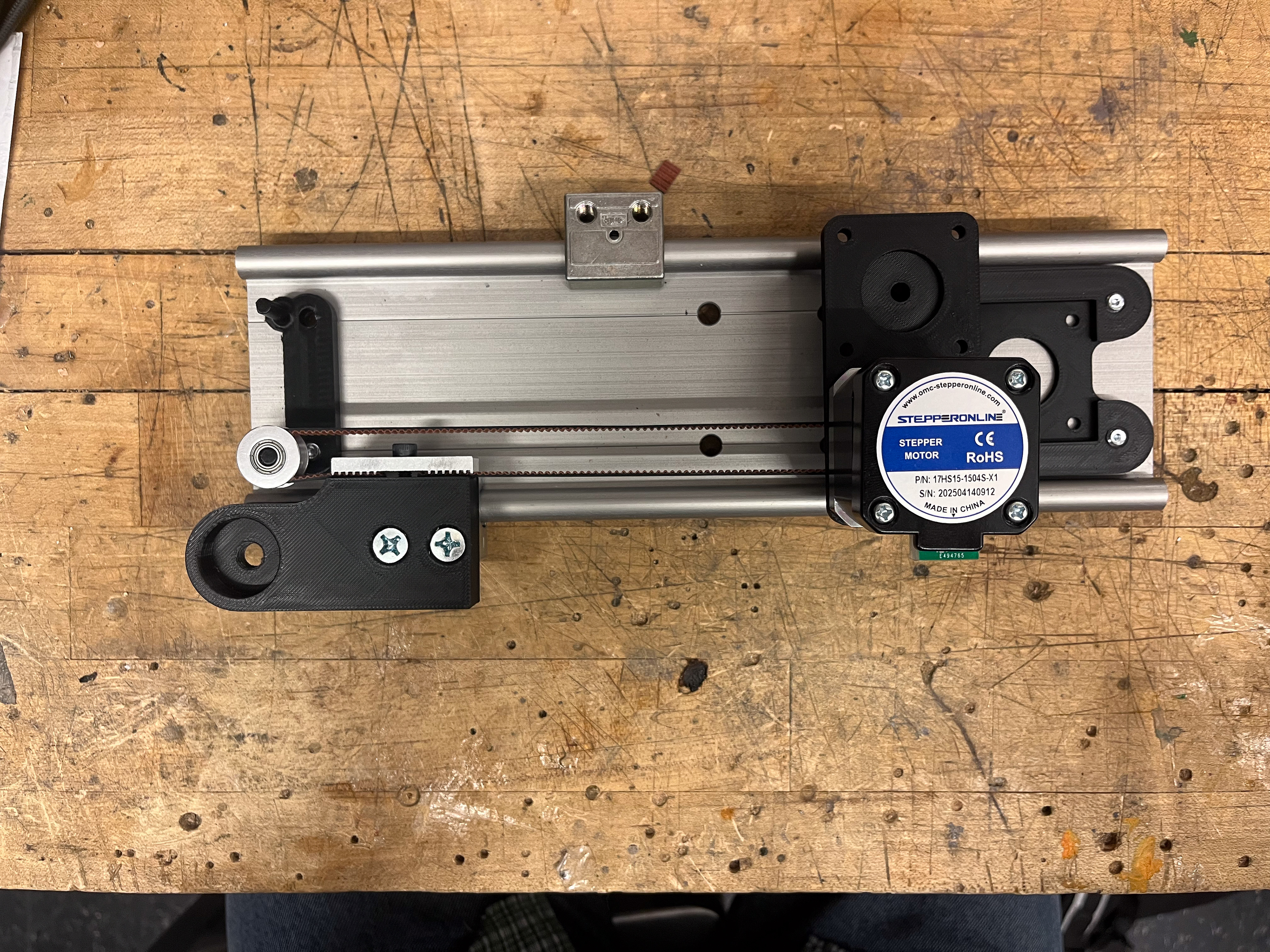
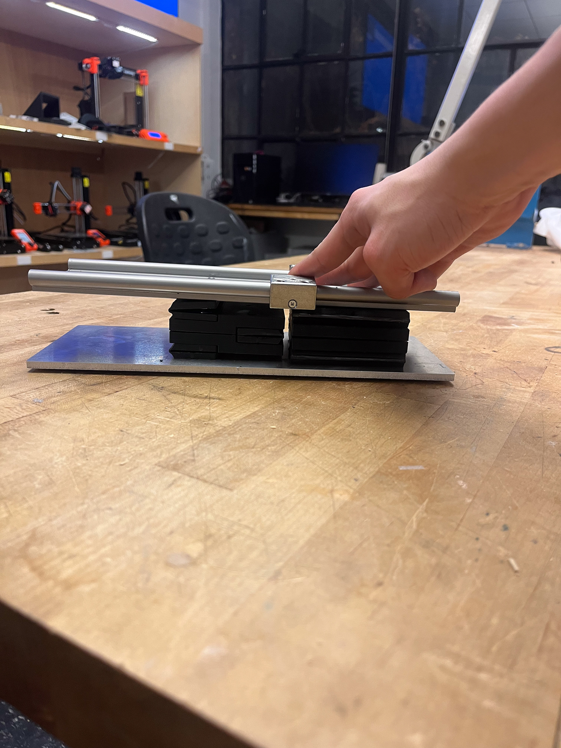
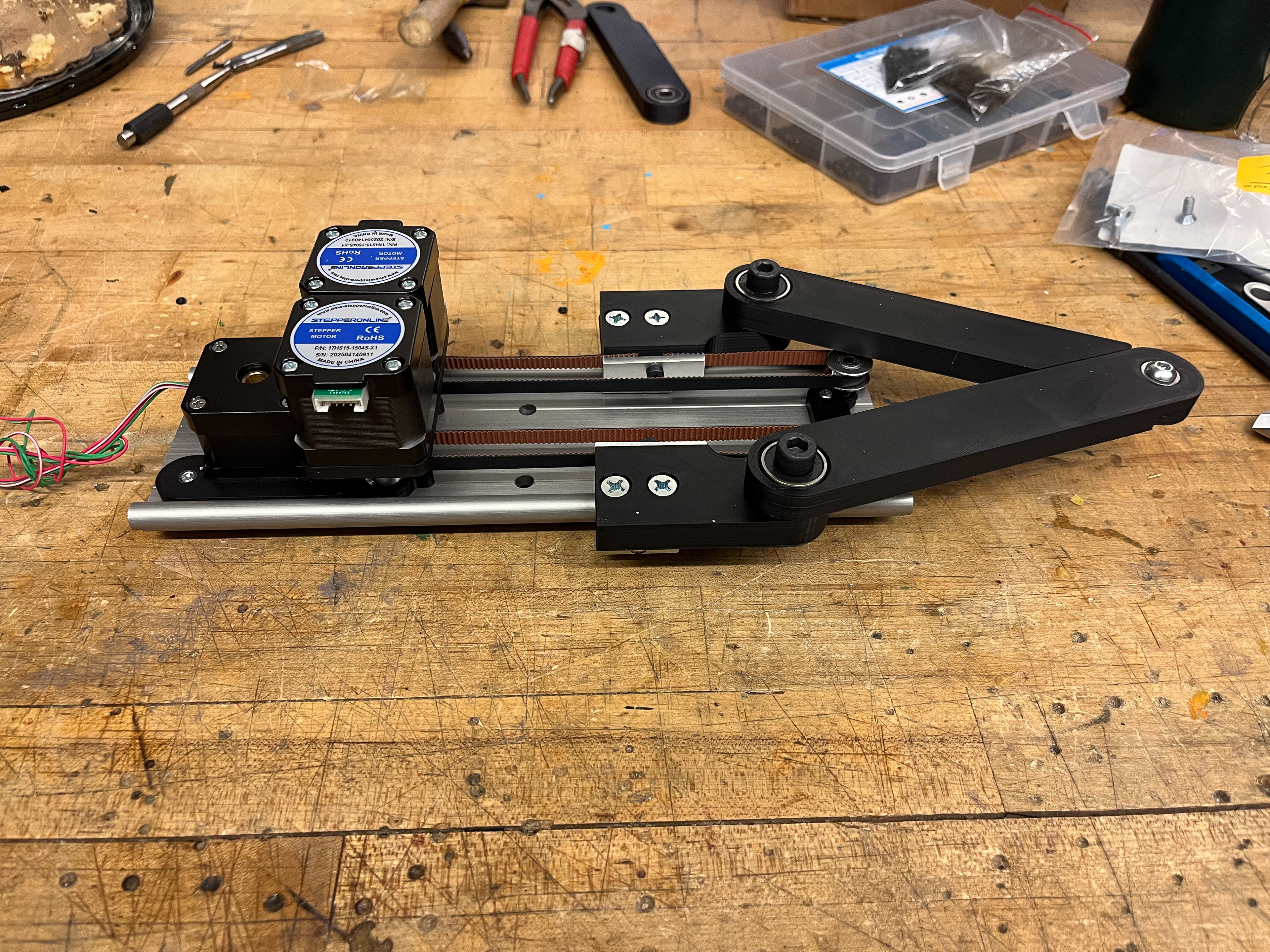
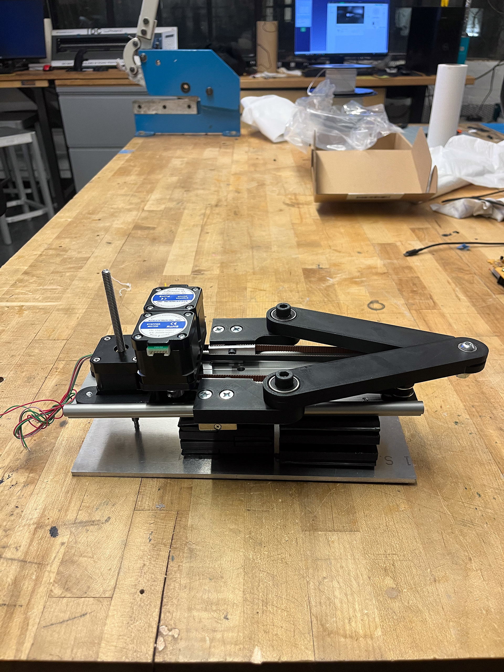
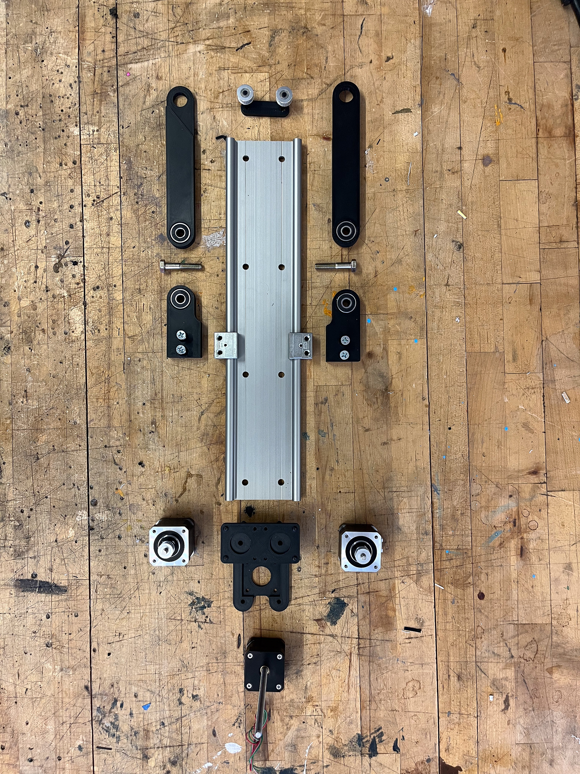
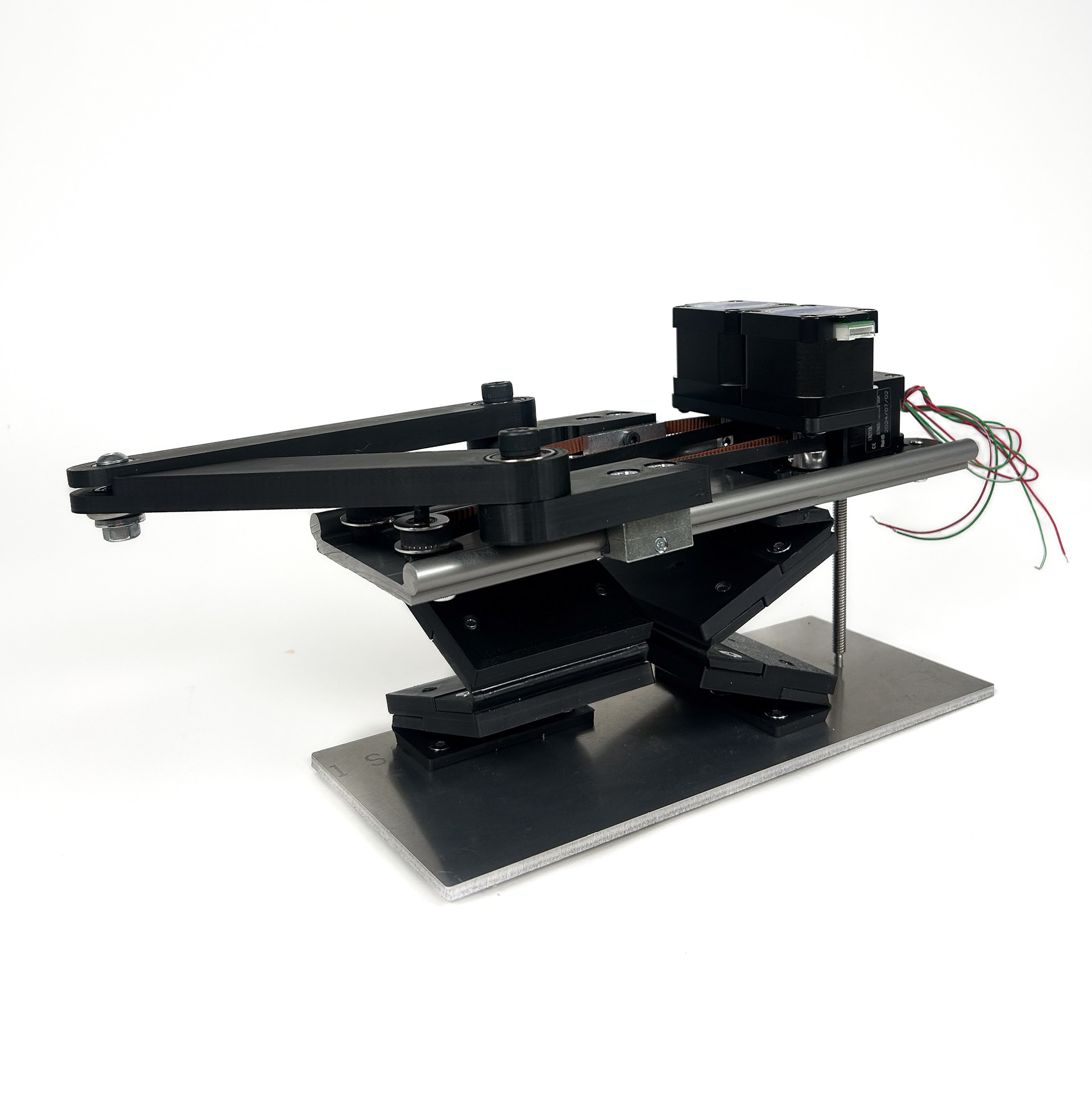
Low-fidelity Prototype
While designing a high-fidelity version of the Sarrus linkage model, we decided to explore a quickly prototyped, lower-cost form factor; this approach allowed for less orthodox building components, such living hinges instead of bearing assemblies and an aluminum extrusion sample instead of typical linear rails. I designed and fabricated the following prototype in approximately five days. A quantification of stiffness and accuracy is in progress - check back later to see more!